Introduction
In October 2022, during an investigation into an incident at a Russian industrial enterprise, samples of previously unseen malware were discovered running on compromised computers of this organization. The names of this malware’s executable files were similar to the names of legitimate software installed on the infected machines, and a number of samples had valid digital signatures. Also, the identified executable files and libraries were processed by the Themida protector to make them more difficult to detect and analyze.
Subsequent analysis of these samples revealed that the identified software is a fairly complex modular backdoor, which we called MataDoor, designed for long-term covert operation in the
Initial infection vector
We presume that the initial vector for introducing the backdoor into the compromised system was a phishing email with a DOCX document attached. The content of this document was relevant to the field of operations of the targeted enterprise. This document contained an exploit for the CVE-2021-40444 vulnerability. The complete attack chain could not be reconstructed from this document; however, the correlation between the time the backdoor activity began and the time the email was sent strongly suggests that this malicious document was the source of the backdoor.
This email is not unique. Similar emails containing documents with exploits for the CVE-2021-40444 vulnerability were sent to Russian defense industry enterprises in August—September 2022. The content of some of them was related to the activities of the attacked enterprises, while others were simply designed to attract the attention of the recipient. All the letters encouraged the user to enable editing in the document, which is a necessary condition for running the exploit.
Below are examples of the documents related to the enterprise’s activities:


The font used in the above documents forces the user to enable editing and change the color to make it more visible. When editing is enabled, a malicious payload is loaded and executed from an attacker-controlled resource, exploiting the CVE-2021-40444 vulnerability. The actual payload could not be obtained because the servers containing it were inaccessible at the time of the investigation.
The documents that simply aimed to attract the recipient’s attention looked like this:

When analyzing the properties of these documents, it was discovered that the URL from which the exploit payload is loaded is HTML-encoded:
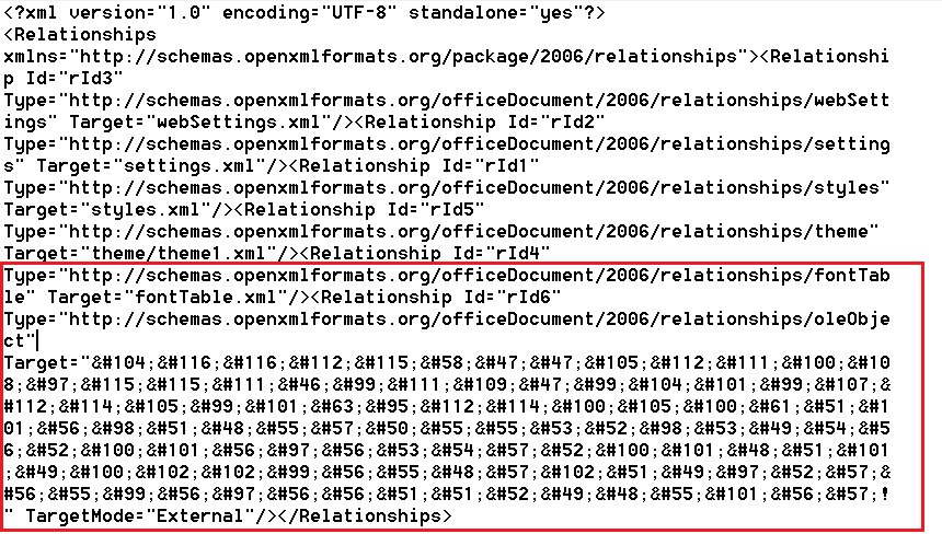
It should be noted that in the analysis of an array of documents exploiting the CVE-2021-40444 vulnerability, this URL encoding method was found only in these documents, which suggests that these mailings may have the same origin.
There are certain similarities between these emails and the phishing emails sent to Russian defense industry enterprises and discovered in September 2021. Information about them has been published by Malwarebytes (https://www.malwarebytes.com/blog/news/2021/09/mshtml-attack-targets-russian-state-rocket-centre-and-interior-ministry). In this report, there was mention of an email with a DOCX attachment, supposedly sent by the organization’s HR department with a request to fill in the table provided in the document:

When editing was enabled, the CVE-2021-40444 vulnerability was exploited, followed by the execution of malicious content.
The September 2021 documents also used HTML encoding for the payload URLs:
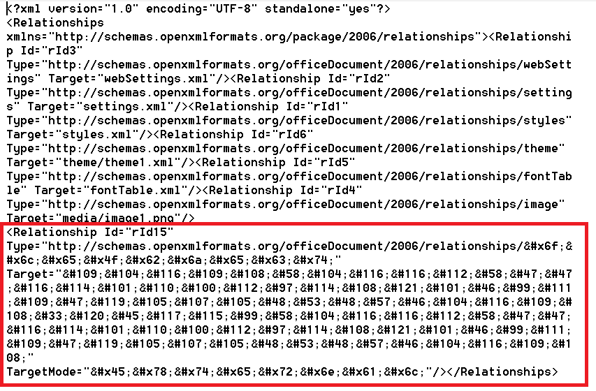
The same method of encoding the payload URL of the malicious documents suggests that the above-mentioned mailing campaigns from 2021 and 2022 were carried out by the same actor.
There are some additional signs that support this assumption:
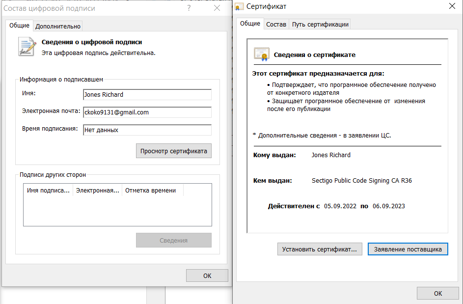
- The payload in the September 2021 campaigns and some instances of the MataDoor backdoor discovered in 2022 were signed with Sectigo certificates.
- The domain names of the payload servers for all the mentioned malicious documents are all registered by the Namecheap registrar. The C2 domain names for MataDoor are also registered by Namecheap.
- All the attacks targeted Russian enterprises in the defense industry.
It is notable that the elements of the network infrastructure used in attacks on different organizations do not overlap. The domains’ registrants’ details are hidden.
Some information about the characteristics of the MataDoor backdoor was published by Kaspersky in the “Southeast Asia and Korean Peninsula” section of the APT Trends Report Q2 2023. In that report, this backdoor, named MATAv5, was associated with the Lazarus group’s activity. In our investigation of the network infrastructure used, we were unable to definitively identify the author of this tool. So we assigned the name Dark River to the group that initiated the attack, based on the name River mentioned in the Author field of some of the phishing documents mentioned above.
MataDoor. Description of the backdoor
1. Launching and persistence
The backdoor is a DLL that, in addition to the standard DllMain function, exports the DllRegisterServer function. This allows the payload to be run when called through the standard Windows Regsvr32 program normally used for registering OLE controls in the system registry. In practice, both functions—DllMain and DllRegisterServer—perform the same actions, initializing the backdoor and running its main execution logic in a separate thread.
However, in all known cases, the backdoor is run using an additional component called loader service, which is a Windows service that runs automatically when the system starts, ensuring the backdoor’s persistence in the system. The loader service component does not perform any actions other than launching the DLL with the backdoor, the path of which is defined in its configuration. The loader’s configuration, like the configuration of the backdoor itself, is encrypted using the AES algorithm in cipher feedback (CFB) mode.
In all examined samples, the decryption key for the configuration is the sequence 29 23 BE 84 E1 6C D6 AE 52 90 49 F1 BB E9 EB, which represents the sequence of the first 16 bytes generated by the linear congruential generator X[n] = (0×343fd × X[n-1] + 0×269ec3) mod 0xffffffff with the seed (X[0]) set to 1. This generator corresponds to the implementation of the rand() function from the Microsoft C Runtime standard library.
It’s worth noting that the components of this malware have distinctive compilation names: loaders are named loader_service_raw_win_intel_64_le_RELEASE.dll, while backdoors are named MATA_DLL_DLL_PACK_**********_win_intel_64_le_RELEASE.dll, where ********** represents a specific date. Variants of backdoors with the following compilation names have been investigated:
MATA_DLL_DLL_PACK_20221013_011_win_intel_64_le_RELEASE.dll,
MATA_DLL_DLL_PACK_20221006_011_win_intel_64_le_RELEASE.dll,
MATA_DLL_DLL_PACK_20221013_011_win_intel_64_le_RELEASE.dll.
Given the presence of the string “MATA” in the compilation name, the backdoor was given the name MataDoor.
As previously mentioned, when installing this malware, the attackers choose the names of the loader and backdoor executable files separately for each compromised host, mimicking the file names of legitimate programs deployed on it. For example, if there is a legitimate executable file named 1cv8.dll in the system, the backdoor file name might be 1cv8u.dll.
In many cases, the names of the loader and the backdoor are also similar. For example: dlpsvc.dll (loader filename) and dlpsvcHelper.dll (backdoor filename).
As mentioned earlier, some backdoor and loader instances were signed with Sectigo certificates:
2. High-level architecture
The examined sample is a modular backdoor. Architecturally, it consists of a kernel (orchestrator) and modules (plugins). The kernel includes the following functionality:
- Data serialization mechanism using its own custom format
- Backdoor configuration management
- Receiving and processing commands from the C2
- Mechanism for performing asynchronous operations
- Plugin management
Let’s take a closer look at each of these components.
3. Plugins
The plugins (modules) used by the backdoor are divided into two categories:
- Functional plugins that implement commands from the C2 that the backdoor can execute.
- Transport (network) plugins that implement network protocols.
Plugins can either be separate PE modules or be embedded—statically linked with the backdoor. During our investigation we found no separate plugins and examined only embedded ones.
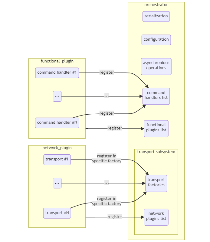
Each plugin has its own identifier, which is unique within the set of plugins in the same category. That is, the identifiers of a transport plugin and a functional one may match, but, for example, the identifiers of two different transport plugins should not match. The identifier is used for registering the plugin in the kernel and for unloading it. Information about the currently registered plugins is maintained by the orchestrator in the form of two lists: one for network plugins and another for functional plugins. Now, let’s examine each of these categories separately.
3.1. Functional plugins
Every functional plugin, regardless of its form, must be registered in the orchestrator’s context. The orchestrator maintains a list of all such plugins, each element of which has the following structure:
    typedef struct
{
    int unknown; // This field was not used in the code.
    int pluginId; // Plugin ID
    void* pluginModulePtr; // Pointer to the loaded PE module of the plugin
    UNLOAD_PROC unloadProc; // Pointer to the plugin unload procedure
    PluginInfo *next;
} PluginInfo;
The pluginModulePtr field contains a pointer to the loaded PE module of the plugin, analogous to the module handle returned by the LoadLibrary call. For embedded plugins, this field is set to 0. In addition to the plugin itself, the orchestrator must also register handlers for the C2 commands that this plugin implements. Each command, along with its corresponding handler, has a unique identifier within the entire set of commands implemented by the backdoor. The plugin registers the command handlers it implements by calling the corresponding API method provided by the orchestrator. These actions are performed during the plugin initialization procedure. The plugin initialization procedure also tells the orchestrator the plugin’s identifier and the address of the plugin unload procedure. An example of such an initialization procedure is shown below:
    int __fastcall Plugins::Bridge::Init(ORCHESTRATOR *ctx, int *moduleId, void *unloadProc)
{
  if ( (ctx->id - 7) > 0x3E0 )
    return ERR_PROC_NOT_FOUND;
  if ( moduleId )
  {
    Plugins::Bridge::PluginId = *moduleId;
    *moduleId = 5;
  }
  if ( unloadProc )
    *unloadProc = Plugins::Bridge::Unload;
  ctx->RegisterCommandHandler(ctx, 500, Plugins::Bridge::RunBridgedClients);
  ctx->RegisterCommandHandler(ctx, 502, Plugins::Bridge::RunAuthServer);
  ctx->RegisterCommandHandler(ctx, 505, Plugins::Bridge::RunRawServer);
  return 0;
}
This procedure initializes the plugin with the identifier 5, which allows a backdoor instance to act as a relay node for transmitting data between other instances of the backdoor. This functionality is implemented through three commands with identifiers 500, 502, and 505. We discuss this in more detail in the corresponding section.
In terms of input, the command handler receives a pointer to the orchestrator’s context, parameters in serialized form (more on serialization in the corresponding section), and the pointer to the variable for recording the command execution status or error code:
SerializedData *__fastcall CommandHandler(
        ORCHESTRATOR *ctx,
        SerializedData *parameters,
        int *pStatus);
The handler returns the results of command execution in serialized form. The composition of serialized elements is specific to each command.
The plugin unload procedure releases various resources used by the plugin and must also remove the commands implemented by the plugin from the list of active commands, which is also done by calling the corresponding orchestrator API function. An example of such a function for the aforementioned module is presented below:
int __fastcall Plugins::Bridge::Unload(ORCHESTRATOR *ctx)
{
  ctx->UnregisterCommandHandler(ctx, 500);
  ctx->UnregisterCommandHandler(ctx, 502);
  ctx->UnregisterCommandHandler(ctx, 505);
  return 0;
}
3.2. Transport (network) plugins
All network protocols used by the backdoor are implemented in transport plugins. Each of these plugins also has a unique identifier with which it is registered with the orchestrator or unloaded. The orchestrator stores information about the network plugins in use in a separate list, the elements of which have the following structure:
typedef struct
{
    int moduleId; // Plugin ID
    int unknown1; // Always equal to 0.
    int factoryId; // Connection factory ID
    int unknown2; // Not used.
    void* moduleBase; // Pointer to PE module of the plugin
    void* unloadProc; // Pointer to the plugin unload procedure
    NetworkPluginInfo* next;
} NetworkPluginInfo;
In addition to the network module identifier itself (moduleId), registration also requires the identifier of an existing connection factory registered in the orchestrator, within which this plugin will operate (parameter factoryId). This allows the factory to create new connections using the protocol implemented by this transport plugin.
If the transport plugin is an embedded one, the moduleBase field is set to 0.
The transport plugin can implement multiple network protocol variants (for example, HTTP and HTTPS). Each implemented protocol variant (or transport in the context of this report) must have its own string identifier (for example, “tcp”, “tcp6”), by which it is specified in the network connection configuration string (see the “Transport subsystem overview” section for more details). The mapping between the string identifier and the procedure for creating the corresponding transport is registered in the respective factory using the initialization procedure of the transport plugin provided by the backdoor’s API. Below is an example of the initialization procedure for a network plugin that implements HTTP and HTTPS transports:
int __fastcall HttpTransport::InitProc(
        NETWORK_TRANSPORT_FACTORY **factories,
        int factoryId,
        _DWORD *pStatus,
        _QWORD *unloadProc)
{
  NETWORK_TRANSPORT_FACTORY *factory; // rbx

  factory = *factories;
  if ( !*factories )
    return ERR_BAD_COMMAND;
  while ( factory->identifier != factoryId )
  {
    factory = factory->next;
    if ( !factory )
      return ERR_BAD_COMMAND;
  }
  if ( !HttpTransport::GetTransportDescriptorStatus )
    CreatePipeNoBlockingMode(&HttpTransport::ControlPipeRead, &HttpTransport::ControlPipeTransportEndpoint, 0i64, 0);
  HttpTransport::GetTransportDescriptorStatus = factory->GetTransportDescriptorsStatus;
  factory->RegisterTransportCreationRoutines(factory, aHttp, HttpTransport::HttpTransport);
  factory->RegisterTransportCreationRoutines(factory, aHttps, HttpsTransport::HttpsTransport);
  HttpTransport::RegisterProxyTransportFactories(factory);
  if ( pStatus )
    *pStatus = 1;
  if ( unloadProc )
    *unloadProc = HttpTransport::Unload;
  return 0;
}
The plugin unload procedure removes the transport creation functions from the factory and releases the resources in use. An example of such a procedure for the “http” network plugin:
int __fastcall HttpTransport::UnregisterFactory(NETWORK_TRANSPORT_FACTORY **factoriesList, int factoryId)
{
  NETWORK_TRANSPORT_FACTORY *factory; // rbx

  factory = *factoriesList;
  if ( !*factoriesList )
    return ERR_BAD_COMMAND;
  while ( factory->identifier != factoryId )
  {
    factory = factory->next;
    if ( !factory )
      return ERR_BAD_COMMAND;
  }
  factory->DeleteTransportCreationInfo(factory, "http");
  factory->DeleteTransportCreationInfo(factory, "https");
  factory->DeleteTransportCreationInfo(factory, "proxy_http");
  factory->DeleteTransportCreationInfo(factory, "proxy_https");
  return HttpTransport::FinalizeProcessingConnections();
}
4. Asynchronous operations
Commands that take a long time to execute are executed asynchronously, in a separate thread. The backdoor stores the Information about all current asynchronous operations in a separate global (within the backdoor instance) list. Information about an asynchronous operation is added to the list before the operation starts and removed after its completion. This information has the following structure:
typedef struct
{
     int state; // Operation state. 1: in progress, 2: completed
     int pluginID; // ID of the functional plugin performing the operation
     int unknown1;
     int workerThreadId; // ID of the thread performing the operation
     HANDLE hWorkerThread; // Handle of the thread performing the operation
     long startTime; // Start time of the operation in Unix timestamp format
     int unknown2;
     int operationId; // Operation identifier
     int unknown3;
     char* operationDescription; // Not used during execution, presumably description of the operation.
     void* asyncOperationRun; // Function that directly performs the operation
     void* asyncOperationFinalize; // Function for releasing resources
     AsyncOperationBasicContext *next;
} AsyncOperationBasicContext;
Each asynchronous operation has its own identifier operationId, which is not related to the identifier of the command that performs the operation. Multiple operations with the same operationId can be executed simultaneously. In the context of an asynchronous operation, the identifier of the plugin that performs it (pluginID) must be specified to avoid unloading the plugin while it is performing the asynchronous operation. In this case, the backdoor waits for the operation to complete before unloading the plugin.
5. Serialization mechanism
The backdoor extensively utilizes its own data serialization system, which is used, for example, to store configurations for both the backdoor itself and its network connections, as well as to transmit commands and the results of their execution. Data serialization is carried out through an API provided by the backdoor’s kernel.
A serialized storage unit has the following structure:
[data size: 4 bytes, big-endian] [key: 4 bytes, big-endian] [serialized data]
Serialized storage units can be grouped together into arrays, in which case they are treated as a single entity from the backdoor’s perspective.
The serialization key is a DWORD. The high-order word indicates the type of the serialized data, and the low-order word serves as the identifier for the storage unit. The same array can contain multiple units with identical keys. In this case, they are accessed using an additional index.
A total of 14 possible data types are used, ranging from 0×01 to 0×0E. Based on the size of the stored data, these types can be categorized as follows:
- 0×01, 0×06: BYTE
- 0×02, 0×07: WORD
- 0×03,0×08, 0×0B: DWORD
- 0×04, 0×09, 0×0A: QWORD
- 0×05, 0xC, 0xD, 0xE: byte array
All fixed-size values (WORD, DWORD, QWORD) are serialized in big-endian format.
The purpose of some types can be inferred from their usage context:
- 0×1: not encountered in the analyzed code.
- 0×2: network connection port number.
- 0×3: 4-byte storage unit without specific properties.
- 0×4: offset relative to some value, such as the beginning of a file.
- 0×5: cryptographic data (public keys, nonce, hash value, and so on).
- 0×6: not encountered in the analyzed code.
- 0×7: not encountered in the analyzed code.
- 0×8: operation/command execution status.
- 0×9: not encountered in the analyzed code.
- 0×A: temporary attributes of operating system objects (processes, files) in Unix timestamp format.
- 0×B: bitmask.
- 0×C: string.
- 0×D: array of containers.
- 0×E: container, with its data area being an array of other serialized units. Containers allow serialized data to be organized into a hierarchical structure of arbitrary depth.
The API for working with this format includes the following functions:
// Concatenate one serialized storage unit with another so that they are in a single buffer and follow one another sequentially.
SerializedData *__fastcall ConcatItems(SerializedData *dstItem,
                                       SerializedData *srcItem);

// Add a storage unit to the container.
SerializedData *__fastcall AddNewItemIntoContainer(SerializedData *container,
                                                   u_long newItemId,
                                                   char *newItemData,
                                                   signed int newItemBufLen,
                                                   DWORD *status);
// Copy a storage unit.
SerializedData *__fastcall CopyItem(SerializedData *srcItem);

// Get the size of a storage unit (including headers).
__int64 __fastcall GetItemSize(SerializedData *item);

// Get the number of storage units with the specified key in a container.
__int64 __fastcall CountItemsInContainer(SerializedData *container,
                                         int itemsKey);

// Get the pointer to the data buffer for the storage unit with the specified key and index.
SerializedData *__fastcall GetItemDataWithDesiredId(SerializedData *items,
                                                    int key,
                                                    int itemIndex)

// Get a copy of the storage unit with the specified key and index from a container.
int __fastcall GetItemDataCopyFromContainer(SerializedData *items,
                                            unsigned int itemKey,
                                            __int64 index,
                                            _BYTE *dst,
                                            unsigned int dstCapacity);

// Get a pointer to the buffer of the storage unit with the specified key and index from a container.
char *__fastcall FindItemPtrWithDesiredId(SerializedData *items,
                                          int key,
                                          int itemIndex);

// Create a new container with the specified key.
SerializedData *__fastcall MakeNewContainer(u_long key);

// Delete the specified storage unit from a container.
__int64 __fastcall DeleteItem(SerializedData *items,
                              int id,
                              int itemsCount);

// Replace the specified storage unit in a container.
SerializedData *__fastcall ReplaceItem(SerializedData *container,
                                       unsigned int key,
                                       int replacedItemIndex,
                                       char *replacementData,
                                       u_long size,
                                       DWORD *status);
6. General workflow of the backdoor
The general workflow of the backdoor is as follows:
6.1. Initialization
During this stage, the backdoor initializes the orchestrator, registers the built-in network and functional plugins, and retrieves its parameters from its configuration. The backdoor’s configuration is a separate block in the initialized data section, encrypted using the AES algorithm in CFB mode with the key mentioned earlier in the “Launching and persistence” section. A pointer to the decrypted configuration is then stored in the orchestrator’s context.
After decrypting the configuration, the backdoor attempts to load the saved configuration. To do this, it extracts from its current configuration the serialized (under the 0xC0037 key) name of a registry key in the HKEY_LOCAL_MACHINE section where the saved configuration is located. When saving, the current configuration is compressed using the LZ4 algorithm and then encrypted with the AES-CFB algorithm, using the same key. If there is no saved configuration—for example, during the first launch—the backdoor uses the configuration extracted from the data section.
Next, a command (key 0xC002F) is extracted from the configuration and executed in the cmd.exe interpreter. In all examined instances of the backdoor, the value of this command in the initial configuration was empty.
6.2. Establishing connection
Next, the backdoor establishes a connection to the C2 based on the network configuration stored in serialized form under the 0xD0033 key. The network configuration may contain several different options for connecting to the C2. In this case, the option used is selected randomly. In the selected connection configuration, its usage counter (serialization key = 0×30035) is increased by 1 and saved. Next, a string that describes the connection to the C2 (serialization key = 0xC0034) is extracted from the selected configuration; based on this string, the backdoor establishes a connection to the C2 and then sends serialized lists of identifiers of all network and functional plugins in use to the C2. The serialization key for the list of functional plugins is 0xD0006; for the network plugin list it’s 0xD0009. Next, the backdoor starts receiving and processing commands. The connection to the C2 uses the agent transport, with authentication of connected clients (see the description of the transport subsystem).
6.3. Command receiving and processing cycle
Commands are transmitted from the C2 to the backdoor in serialized form. The total size of the command is transmitted first (4 bytes, byte order: big-endian), followed by the command itself. The command code has a size of 4 bytes and is serialized with key 0×30005. The data which is obtained during command execution and has to be sent to the C2 is also serialized into the container with key 0xE0002. The code of the operation execution status (key = 0×80003) is also added to this container, and then the result is sent to the C2 and the cycle repeats.
In case of errors, the connection to the C2 is reset and re-established according to the procedure described above in Section 6.2.
Below is an example of an empty command handler from the Processes plugin (see the corresponding section).
SerializedData *__fastcall Processes::EmptyCommand(
        ORCHESTRATOR *ctx,
        SerializedData *parameters,
        int *pStatus)
{
  int status;
  SerializedData *operationResultContainer;

  status = 0;
  operationResultContainer = ctx->MakeNewContainer(OPERATION_RESULT_CONTAINER);
  if ( !operationResultContainer )
    status = ERR_OUT_OF_MEMORY;
  if ( pStatus )
    *pStatus = status;
  return operationResultContainer;
}
Here is the minimum necessary set of actions that the command handler must perform:
- Create a container in which the results of command execution will be serialized. In this case, it does not contain any storage units.
- Write the operation execution status or error code to the variable pStatus.
- Return the container with the command execution results.
7. Deferred commands
The backdoor has an additional ability to periodically execute a set of additional commands, outside the main cycle of their reception and processing. Such commands are hardcoded in the backdoor configuration, and their composition can be changed only by changing the whole configuration.
A certain time interval is set for the execution of deferred commands, which is specified by the backdoor operator (commands with ID = 109 and 110 of the Management plugin, see the description below). If this interval is not set (equal to 0), deferred commands are not executed. Checking for this interval and calling of the deferred command handler occurs after execution of a successive command from C2 in the main cycle of command reception and processing.
If the time interval for deferred commands is not 0, an attempt is made to execute commands. In case of failure, the handler waits for some time (three seconds by default), and then attempts to execute the commands again until the time interval is exhausted or the commands are successfully executed.
In addition, the operator can set a specific start time for deferred commands (command with ID = 110 of the Management plugin), which can also be referred to as the “wake-up time.” If this time is specified, the deferred command handler waits until the specified wake-up time comes and only then proceeds to execution. Accordingly, the whole cycle of receiving and processing commands from the C2 is suspended for the time of waiting.
A simplified listing of the deferred command handler is shown below:
__int64 __fastcall ExecuteScheduledTasks(ORCHESTRATOR *this, unsigned int scheduledCmdExecutionTimeInterval)
{
  ...
  config = this->configuration;
  commandsExecutionTimeFrame = scheduledCmdExecutionTimeInterval;
  sleepIntervalInSeconds = 0;
  wakeUpTime = 0i64;
  timeWhenExecutionBegun = time64(0i64);

  if ( GetItemDataCopyFromContainer(config, SLEEP_TIME_IN_SECONDS, 0i64, &sleepIntervalInSeconds, 4u) < 0  || sleepIntervalInSeconds > 7200 )
  {
    sleepIntervalInSeconds = 3;
  }

  if ( GetItemDataCopyFromContainer(config, WAKE_UP_TIME, 0i64, &wakeUpTime, 8u) > 0 && wakeUpTime )
  {
    while ( time64(0i64) < wakeUpTime )
    {
        Sleep(1000 * sleepIntervalInSeconds);
    }
    wakeUpTime = 0i64;
    ReplaceItem(config, WAKE_UP_TIME, 0, &wakeUpTime, 8u, 0i64);
  }

  while ( timeWhenExecutionBegun + commandsExecutionTimeFrame > time64(0i64) )
  {
    ...
    if ( ExecuteScheduledCommands(this) >= 0 )
      return 4i64;
    Sleep(1000 * sleepIntervalInSeconds);
  }

  return 1i64;
}
The array of deferred commands is serialized in the backdoor configuration with the key 0xD0024. Each element of this array includes the following values:
| 0x30025 | Command identifier |
| 0xD0028 | Command parameter array |
| 0x30026 | If this parameter is 0, this command is not executed |
| 0x30027 | If this parameter equals 1, execution of deferred commands is terminated |
The results of execution of deferred commands are serialized in the array with the 0xD002A key. Each element of the array includes the following elements:
| 0x30025 | Executed command identifier |
| 0x4003B | Command execution termination time |
| 0xE0002 | Container with the command execution results |
The results of the execution of deferred commands are sent to the C2 by a separate command with ID = 105. Once sent, the container with the results is released. If the number of entries in this container exceeds 1,000, the old entries are deleted.
8. Descriptions of plugins
In this section, we will examine the functionality of all the plugins used in the analyzed instances of the backdoor. The plugin names are based on their functionality and are not found in the code itself.
8.1. Management
Let’s take a look at the Management plugin, which has the identifier pluginId = 1. Its primary functionality is to manage the backdoor orchestrator. There are a total of 18 commands here, with the IDs from 100 to 117. The unique feature of these commands is that all the data handlers for them are obfuscated using the Themida virtual machine to complicate analysis of the orchestrator control logic.
- Command with ID = 100 loads and registers the specified plugin. It takes the following parameters:
| 0x30007 | Plugin identifier |
| 0x50065 | Buffer with a PE module that implements the plugin’s functionality |
| 0xC0066 | Name of the plugin initialization function (exported by the PE module of the plugin) |
The specified PE module is reflectively loaded into the address space of the backdoor process, after which the specified plugin initialization function is called. The newly loaded plugin is then registered in the orchestrator under its identifier.
- Command with ID = 101 unloads the specified plugin. It takes the plugin identifier as a parameter (serialization key = 0×30007). When unloading the plugin, it waits for all asynchronous operations performed by the plugin to complete.
- Command with ID = 102 loads the specified transport plugin. It takes the following parameters:
| 0x30007 | Transport plugin identifier |
| 0x30014 | Connection factory identifier (see the “Transport subsystem architecture” section) |
| 0x50065 | Buffer with a PE module that implements the plugin’s functionality |
| 0xC0066 | Name of the plugin initialization function (exported by the PE module of the plugin) |
Similarly to the command with ID=100, the specified PE module is reflectively loaded into the address space of the backdoor process, and the plugin initialization function is called. The plugin is then registered in the specified connection factory under its identifier.
- Command with ID = 103 unloads the specified network plugin, removing it from the specified factory. It takes the following parameters: network transport factory identifier (0×30014) and plugin identifier (0×30007).
- Command with ID = 104 takes as input a connection factory identifier (serialization key 0×30014) and creates a new (empty) connection factory with the specified identifier.
- Command with ID = 105 sends the results of scheduled command execution to the C2, along with detailed information about the current machine. The container with the result of the command contains the following entries:
| 0x4007B | Constant that varies in different samples (for example, 0×846A9F5EA9D10C3C), possibly part of the build identifier |
| 0x3007A | Constant that varies in different samples (for example, 0×780C2714), possibly part of the build identifier |
| 0x30079 | Constant that varies in different samples (for example, 0×03), possibly part of the build identifier |
| 0xC0081 | Computer name |
| 0xC0082 | User name |
| 0xC0083 | IP address of the local network adapter (as a string) |
| 0x50085 | MAC address of the local network adapter |
| 0x50088 | Information about the OS version in the form of the OSVERSIONINFOEXW structure |
| 0x30086 | Major OS version number |
| 0x30087 | Minor OS version number |
| 0x8003A | Difference in seconds between local time and UTC time |
- Command with ID = 106 sends the current configuration of the backdoor to the C2.
- Command with ID = 107 updates the backdoor configuration. The new configuration is specified in the command parameters (serialization key = 0xE001E). During command execution, it tests newly configured network connections to the C2. The test results for each network connection variant are sent to the C2, serialized as follows:
| 0xC0034 | Configuration string of the tested connection |
| 0x80003 | Result code of the connection attempt using the specified transport |
- Command with ID = 108 has an empty handler.
- Command with ID = 109 sets the time interval during which a dedicated function will attempt to execute deferred/scheduled commands (parameter key = 0×30064). The function also stops these attempts upon successful execution of these commands. The time interval is specified in minutes. The command serializes the value of the set parameter (key = 0×30064) into the command result container. The specified time interval cannot exceed 180 days.
- Command with ID = 110 sets the time interval for executing deferred commands (similarly to the command with ID = 109, the parameter key is 0×30064), and also sets the wake-up time in Unix timestamp format (parameter key = 0×40022). The wake-up time is calculated as the sum of start time of the specified command execution and the specified time interval for executing deferred commands. After the execution of the specified command is completed, the cycle of receiving and processing commands from the C2 is suspended until the wake-up time.
- Command with ID = 111 sets the parameter with the key 0×30021 in the backdoor configuration, the purpose of which is unknown.
- Command with ID = 112 sets the parameter with the key 0×30020 in the backdoor configuration, the purpose of which is unknown.
- Command with ID = 113 adds new configurations of network transports for communication with the C2, specified in the command parameters (key = 0xC0034). During this, each of the specified configurations is tested by creating a test transport (transport type AUTH), which attempts to connect to the C2. Test results—a string with the network transport configuration (key = 0xC0034) and the result code of the connection attempt using the specified transport (key = 0×80003)—are sent to the C2 via the connection currently in use.
- Command with ID = 114 obtains the identifiers of the current and parent processes, which it serializes into the command result container with keys 0×3008C and 0×3008D, respectively.
- Command with ID = 115 stops the receiving and processing of commands from the C2 until the next backdoor launch. The constant “0×1” is serialized with key 0×3006B into the command result container.
- Command with ID = 116 collects data on all current asynchronous operations, serialized in the following format:
| 0x30090 | Identifier of the thread performing the asynchronous operation |
| 0x3003E | Identifier of the asynchronous operation in progress |
| 0xC0091 | Description of the asynchronous operation in progress |
| 0x3003D | Operation status: started / in progress / completed |
| 0x3003F | Identifier of the plugin that performs the operation |
The array of received data for each asynchronous operation is serialized with key 0xD003C into the command result container.
- Command with ID = 117 has an empty command handler.
8.2. Remote Shell
This plugin has pluginId = 5 and provides only two functions that implement the remote command line mechanism.
- Command with ID = 200 starts a process with the command line specified in the parameters (serialization key = 0×C00C8). The result of this command’s execution is everything that the running process outputs to stdout and stderr, serialized with key 0×C0004, as well as the execution status of the operation or the error code that occurred when starting the process (key = 0×80003).
- Command with ID = 201 launches a remote command line by executing cmd /c start /b <specified command line> and redirecting stdin and stdout to the remote host. If the remote command line process is already running, the command redirects stdin and stdout of that process to the specified remote host. Command parameters:
| 0x300CE | ID of the process whose stdin/stdout need to be redirected to the remote host |
| 0xС00СD | Command line to start the new process whose stdin/stdout will be redirected to the remote host |
| 0xС00СС | String of the connection configuration to the remote host (more details in the “Transport subsystem architecture” section) |
| 0x300CA | If this parameter is non-zero, client authentication is required when establishing a connection to the remote host (see the description of the client and agent transports) |
If the process ID specified in the parameters is 0, a new process with the specified command line is started. Otherwise, the command line is ignored.
8.3. Processes
This plugin has the identifier pluginId = 7 and is designed to work with processes. It implements the following commands:
- Command with ID = 400 performs the same operations as the command with ID = 401 (see below) but using the IWbemServices interface. Also, there is a slight difference in the information collected about the running system processes. The command line with which the process was launched (serialization key = 0xC0064) is added to the information specified in the description of the command with ID = 401.
- Command with ID = 401 retrieves information about each running process in the system. The collected array of data is serialized with key 0xD003C into the container. The number of processes whose information is collected in this container does not exceed 256. When the specified threshold is reached, the intermediate result is sent to the C2, after which the collection of information continues. If the information collection is completed, and the number of processes whose information is recorded in the container is less than 256, the container is sent to the C2 in the usual manner, along with the command execution result (see the “Command receiving and processing cycle” section). The information collected about each process is as follows:
| 0x30066 | Process ID |
| 0x3006A | Parent process ID |
| 0xC006B | Name of the executable file of the process in UTF-8 encoding |
| 0x80065 | Process session ID |
| 0xA006C | Process creation time in Unix timestamp format |
| 0xC006D | Domain of the user on whose behalf the process was created |
| 0xC006E | User on whose behalf the process was created |
| 0x3006F | Processor architecture ID of the current system |
| 0x30070 | Bit depth of the current system processor |
The backdoor uses the following processor architecture identifiers:
| X86_64 | 1 |
| ARM, ALPHA | 2 |
| PowerPC | 3 |
| MIPS | 4 |
| SHX | 6 |
| IA32, IA64 | 7 |
| Microsoft Intermediate Language | 8 |
| Neutral | 9 |
- Command with ID = 402 takes a process ID as a parameter (serialization key = 0×30066) and terminates the execution of the process with the specified ID.
- Command with ID = 403 creates a process with the specified command line on behalf of the user who created the specified session (or the process with the specified ID). The parameter with key 0×3006A holds the ID of the parent process of the newly created process. The command takes the following parameters:
| 0xC0064 | Command line of the process to be run |
| 0x80065 | ID of the session in which to run this process |
| 0x30066 | Process ID. The new process will be created on behalf of the user who created the process with the specified ID if the session ID is not specified (less than 0) |
| 0x3006A | ID of the process that will be specified as the parent of the newly created process |
As the result, the command returns serialized ID of the newly created process (serialization key = 0×30066).
- Command with ID = 404 is empty and does not perform any substantive actions.
- Command with ID = 405 performs an asynchronous operation specified in an external library (DLL). Command parameters:
| 0x50069 | Buffer with the DLL performing the asynchronous operation |
| 0xC0067 | Name of the function performing the asynchronous operation. Exported by the specified DLL. |
| 0xC0064 | String parameter passed to the function performing the asynchronous operation (presumably the description of the operation) |
The command handler reflectively loads the specified DLL into the memory of the current backdoor process, calling the entry point (presumably DllMain) with fdwReason = DLL_PROCESS_ATTACH as a parameter. After loading, it performs an asynchronous operation by calling, in a separate thread, the exported DLL function whose name is specified in the command parameters. The code for performing this operation is provided below:
int __fastcall Processes::InvokeExternalAsyncOperation(EXTERNAL_MODULE_ASYNC_OP_CONTEXT *ctx)
{
  __int64 opDescription;
  void (*externalAsyncOperation)(void);

  operationDescription = ctx->operationDescription;
  externalAsyncOperation = ctx->externalAsyncOperation;
  if ( opDescription )
    (externalAsyncOperation)(0, 0, operationDescription, 0);
  else
    externalAsyncOperation();
  return 0;
}
Upon completion of the asynchronous operation, the DLL is unloaded from memory.
8.4. Filesystem
This plugin has the identifier pluginId = 9 and implements functions for working with the file system via the following commands:
- Command with ID = 300 collects information about the specified file or directory. It takes the following parameters:
| 0xC0064 | Path of the specified file or directory |
| 0x30070 | Maximum number of files or directories whose information will be included in the final result. By default, it is set to 1024 |
| 0x3007B | Flag regulating the output data format, hereinafter referred to as the format flag |
| 0x3007E | Unknown parameter, not used when executing the command |
If the path is not specified, it returns a list of logical disk names with information about their types, obtained through the API call GetDriveTypeA(). If the object with the specified path is a file, the command collects and serializes the following data:
| 0x30067, or 0xB007C if the format flag is set | File attributes: whether it is a directory, read/write/execute permissions (the mode field of the _stat64 structure in the SYS\STAT.H header) |
| 0xС006E | File owner account name |
| 0xC007D | File owner account domain name |
| 0x4006C | File size |
| 0xA0069 | File modification time in Unix timestamp format |
| 0xA0068, included in the result if the format flag is set | Last file access time in Unix timestamp format |
| 0xA006A, included in the result if the format flag is set | File creation time in Unix timestamp format |
| 0xС0066 | File name |
The collected information is serialized into the container with key 0xD003C if the format flag is set, or with key 0xD006D otherwise.
If the specified file system object is a directory, the function obtains the above information for each file or subdirectory located in it (non-recursively). It should be noted that the procedure used to obtain the owner’s account name and file owner’s domain requires the SeBackupPrivilege privilege.
- Command with ID = 301 can be used to send large files from an infected machine to the C2, as well as to track changes in files of interest to the backdoor operator. The command takes the following parameters:
| 0xC0064 | File path |
| 0x4006B | Offset inside the specified file |
| 0x3007A | Unknown parameter, not used when executing the command |
| 0x50071 | MD5 hash of the part of the file which starts at byte zero and ends at specified offset |
The command is executed as follows:
- Calculate the MD5 hash of the file contents from byte zero to the specified offset.
- If the calculated hash matches the specified one, send to the C2 information about the file along with its contents starting from the offset specified in the parameters. If the calculated hash differs from the specified one, send to the C2 the entire file contents along with its metadata.
Information about the file includes the following serialized data:
| 0x4006B | Current offset inside the file, starting from which the data was read |
| 0x4006С | File size |
| 0xA006A | File creation time in Unix timestamp format |
| 0xA0069 | File modification time in Unix timestamp format |
| 0xA0068 | Last file access time in Unix timestamp format |
| 0x80003 | Status of the current operation (error code or 0 if successful) |
- Command with ID = 302 can be used to download large files from the C2 to an infected machine, or to synchronize changes between versions of the same file on the C2 and on the infected machine. The command takes the following parameters:
| 0xC0064 | File path |
| 0x30076 | Size of the buffer that will be used to transfer the file contents |
| 0x30067 | Unknown parameter, not used when executing the command |
The command is executed as follows:
- Send to the C2 the file size (key = 0×4006B), the MD5 of the file contents (key = 0×50071), and the status of the file open operation (key = 0×80003).
- Receive from the C2 the offset within the specific file (key = 0×4006B) where the data received from the C2 will start overwriting the file contents, and the size of this data (key = 0×40006C).
- Command with ID = 303 can be used to send to the C2 the contents of a specific file or of all files residing directly in a specific directory (files in subdirectories are not processed). The command can be used when the operator needs to track changes made to the contents of a specific directory and send only modified or newly created files to the C2.
It takes the following parameters:
| 0xC0064 | Path of the specific file system object (file or directory) |
| 0x50072 | Hash table containing data on the state of files (detailed below) |
| 0xC0077 | Mask of the files to be ignored during the command execution (in the format of the WinAPI function PathMatchSpec) |
The structure containing file state data looks as follows:
typedef struct
{
    __int64 key;                 // Key calculated as the djb2 hash of the file path
    __int64 offsetInFile;        // Offset within the file
    __time64_t modificationTime; // File modification time
    int fileContentsMd5[4];      // MD5 of the file contents
} FILE_STATE;
The hash table of the specified structures describes the files that were previously sent to the C2. The structure fields reflect the file state from the last time the file was sent.
Please note that when calculating the specified key using the djb2 algorithm, the special characters ” * ? > < : are replaced by the character _ and the character \ is replaced by /.
During command execution, the following actions are performed for each file from the specified directory:
- If the file path matches the mask specified in the parameters (key = 0xC0077), the file is ignored.
- The algorithm specified above is used to calculate the key based on the file path.
- Based on the calculated key, the hash table is searched for an entry that matches the specific file. If an entry cannot be found, the file is subsequently sent in its entirety.
- If the MD5 hash of the file contents and the modification date match the corresponding fields in the found hash table entry, the file contents starting with the specified offset are sent. Otherwise, the file is sent to the C2 in its entirety.
- The following serialized file information is sent to the C2:
- Either the entire contents of the file or the contents starting at the specified offset (based on the conditions of steps 4–5) are sent to the C2.
Prior to sending the files to the C2, serialized metadata on execution of the current operation is also sent:
| 0x4006C | Total size of the transmitted files |
| 0x80003 | Status of the operation (always equal to 0) |
| 0x30074 | Number of files whose contents will be transmitted |
| 0x4006B | Total volume of data that will be transmitted by current command (this volume may be different than the cumulative size of files because some files may be transmitted only partially) |
The workflow presented above and the scope of transmitted data are also retained if the command parameter is a file path.
- Command with ID = 304 takes file path (key = 0xС0064) as input. It fills the first 0×10000000 bytes of the specific file with zeros if the file size is larger than 0×10000000 bytes. Otherwise, it completely fills the specific file with zeros.
- Command with ID = 305 takes path of the original file and path of the modified file (key = 0xC0064) as input. It copies the creation time, last access time and last write time of the original file and sets them as the corresponding attributes of the modified file.
- Command with ID = 306 takes directory path (key = 0xC0064) as input. It creates a directory with the specified path.
- Command with ID = 307 deletes the specified files or directory. It takes the following parameters:
| 0xC0064 | File path, directory path, or mask in the format of the WinAPI function PathMatchSpec |
| 0x30067 | Flag; if 0, the preceding parameter is interpreted as a directory path, otherwise it is interpreted as a file name mask |
If the object at the specified path is a file, it is simply deleted. If a directory resides at the specified path, the following occurs:
- If no mask is specified, the function deletes the specified directory together with all its contents.
- Otherwise, the files whose paths match the specified mask are recursively deleted from the directory. If the name of a subdirectory matches the mask, the subdirectory is completely deleted with all its contents.
The command execution result includes data on the number of files to be deleted and the number of files actually deleted. This data is serialized with key 0×30074.
- Command with ID = 308 collects information about the specified directory. It takes a directory name (key = 0xC0064) as a parameter. It returns the total size of files residing in the specified directory, the total number of subdirectories, and the total number of files in the directory. The command execution result is a string serialized with key 0xC0004:
    ...
    GetDirectoryInfo(dirName, &totalFilesSize, &dirsNum, &filesNum);
    sprintf_s(Buffer, 0x1000ui64, "%lld bytes, %d dirs, %d files\n", totalFilesSize, dirsNum, filesNum);
    operationResult = ctx->AddOrReplaceItem(operationResult, OPERATION_RESULT_STRING, 0i64, Buffer, -1, &err);
    ...
- Command with ID = 309 copies the specified directory. Command parameters:
| 0xC0064 | Source directory path or mask in the format of the WinAPI function PathMatchSpec |
| 0xC0064 | Target directory path |
| 0x30067 | Flag; if 0, the first parameter is interpreted as a directory path, otherwise it is interpreted as a file name mask |
If the source directory path is specified by a mask, the files matching the specified mask are copied. The command execution result includes the total number of files to be copied and the total number of files actually copied. This data is serialized with key 0xC0004.
- Command with ID = 310 moves the specified directory. The parameters, returned results, and workflow are analogous to the command with ID = 309.
- Command with ID = 311 takes file path (0xC0064) as input. The command reads the file and sends its contents to the C2. If the file size does not exceed 4096 bytes, the command serializes the file contents (key = 0xC0004) into the command result container. Otherwise, it sends the file contents in parts after serializing them as follows:
| 0xC0004 | Next part of the file, with a size of no more than 4096 bytes |
| 0x3000B | Data end flag. If set to 0, the current part of the file is the last part |
- Command with ID = 312 reads text files and sends them to the C2. The group of commands working with text files was likely implemented to send the results of other commands saved in these files to the C2. Command parameters:
| 0xC0064 | Text file path |
| 0x30081 | Number of strings to be read |
| 0x30082 | String length |
If the number of strings to be read from the file is not zero, the function reads the specified number of strings from the file and sends them to С2 after dividing them into buffers of 4096 or less bytes and serializing them similarly to the command with ID=311. Otherwise, a string with the length specified in the command parameters but not more than 4096 bytes is read from the specified file and then serialized (key = 0xC0004) into the command result container.
- Command with ID = 313 reads data starting from a specific string in a text file. Command parameters:
| 0xC0064 | Text file path |
| 0x30081 | Number of strings that must be skipped |
| 0x30082 | Initial offset within the file |
| 0x30083 | Flag indicating the count direction (0 means that the count starts from the end of the file, otherwise the count starts from the beginning of the file) |
The command reads the contents of the text file beginning with the specified offset in the file and skipping the specified number of strings, and then sends the contents to the C2.
If the specified count direction flag is not zero, the initial offset is counted from the beginning of the file. In this case, the command then skips the specified number of strings (treating CRLF as line end) and sends the remaining part of the file to the C2.
If the specified count direction flag is zero, the initial offset is counted from the end of the file. In this case, the command skips the specified number of strings, read in the reverse direction from the current position toward the start of the file. Then the part of the file spanning from the resultant position to the end of the file is sent to the C2.
The file contents are serialized and sent to С2 similarly to the commands with IDs 311 and 312.
- Command with ID = 314 implements an asynchronous operation to get a listing of the specified directory. The result is saved to a text file. Command parameters:
| 0xC0064 | Directory path |
| 0xC0064 | Name of the text file used to save the results |
| 0x30074 | Maximum object nesting depth |
| 0x30083 | Flag indicating the count direction (0 means that the count starts from the end of the file, otherwise the count starts from the beginning of the file) |
For the specified directory, the command recursively collects the following information and saves it to the specified file:
- Last write date (year, month, day, hour, and minute specified as a string in the format YYYYMMDDhhmm)
- File size
- File name
- Object nesting depth relative to the original directory
Note that the function used to collect the specified information has the capability to exclude the names of files and directories from being processed. However, this option is not used in this command.
- Command with ID = 315 archives the specified files. It is executed asynchronously. Command parameters:
| 0xD006D | Array of paths of the files that must be archived |
| 0x30074 | Size of the array containing the paths of files, in bytes |
The file paths are specified as an array of consecutive structures each describing a string. Structure format: <path length, 4 bytes><file path>. Files from the specified array are put into a consolidated ZIP archive whose path is defined by the last element of this array. The progress of the operation is written to a log file whose name has the following format: <ZIP archive name>.<ZIP archive name length in hexadecimal format> When the operation starts, the string “begin <ZIP file name>” is written to the log file. When the next file is processed, its name is written to the log file. If the next object from the specified array is a directory, it is put into the archive recursively. If a file cannot be archived for some reason, the string “skipped <file name>” is added to the log file. The command execution result is a string serialized with key 0xC0004: “Zip <number of directories> Dir(s), <number of files>File(s) to <ZIP archive name>”.
8.5. Netscan
This plugin has the identifier pluginId = 4 and provides the capability to get various network environment information. It implements a total of 8 commands, which are examined in detail below.
- Command with ID = 2000 checks the availability of the remote host with the specified IP address and port by attempting to connect to it over the TCP protocol. Parameters:
| 0xD006D | Remote host IPv4 address |
| 0x30074 | Remote host port |
| 0x30067 | Local port |
| 0x30069 | Connection timeout, in seconds |
Depending on whether or not a connection was established, the command execution result is either the “SUCCESS” or “FAILED” string serialized with key 0xC0004.
- Command with ID = 2001 performs an asynchronous operation that gets the MAC addresses for the specified list of IPv4 addresses. Command parameters:
| 0x30074 | Size of the structure containing command parameters |
| 0xD006D | Structure containing command parameters |
Command parameters are defined as a separate structure as shown below:
typedef struct
{
     int flags;
     unsigned int initialHostIpv4Addr;
     int hostsInfoSize;
     char outFilePath[1024];
     int waitTimeout;
     int localPort;
     int remotePort;
     char hostsInfo[];
} NETSCAN_OPERATION_PARAMETERS;
For each IPv4 address from the array specified in this structure, the command handler retrieves its corresponding MAC address. IP addresses are specified in the hostsInfo field as strings separated by the CR character. In this case, the DESIRED_HOSTS_AS_STRING_LIST (0x20) flag is set in the flags field.
If this flag is not set, IP addresses are specified by a range with an initial value (initialHostIpv4Addr) and the number of addresses (hostsInfoSize) whose information is required. Each successive address is obtained by adding 1 to the preceding address. The result is a buffer containing strings that look as follows: IP\tMAC\r\n<IP address>\t<MAC address>\r\n. If the WRITE_RESULT_TO_FILE (0x10) flag is set in the flags field, this buffer is written to a text file whose path is specified in the outFilePath field of the NETSCAN_OPERATION_PARAMETERS structure. If the flag is not set, the buffer is serialized with key 0xC0004 into the command result container.
Likewise, if the GET_DESIRED_INFO_LOCALLY (0x40) flag is set in the flags field, the operation receives the local IP-to-MAC mapping table available on the host (via the API call GetIpNetTable). Otherwise, the necessary information is obtained by sending ARP requests.
- Command with ID = 2002 takes the same parameters as the command with ID=2001. It implements an asynchronous operation that checks the availability of the specified network port (the remotePort field of the NETSCAN_OPERATION_PARAMETERS structure) on a set of network hosts specified by the list of IPv4 addresses. The list of IPv4 addresses is specified the same way as in the previous command. This results in a buffer containing strings that look as follows: IP:PORT\tSTATUS\r\n<IPv4 address>:<port>\t<SUCCESS|FAILED>\r\n. The result is saved the same way as in the command with ID=2001. The operating logic is nearly identical for both commands. The only difference is that the GET_DESIRED_INFO_LOCALLY (0×40) flag is not relevant for this command because the performed operation always involves network interaction with specified hosts.
- Command with ID = 2003 takes the same parameters as the command with ID=2001. It implements an asynchronous operation that collects the following data for each IPv4 address from the list specified in the parameters:
- — Host domain name (if available)
- — delay: total time of packet transmission from the local machine to the specified network host and back (in milliseconds)
- — ttl: time to live of a packet sent from the specified network host to the local machine
- The delay and ttl values are obtained by sending an ICMP echo request to the specified network host. The delay is calculated as the difference between the time when the ICMP echo request is sent and the time when a response is received from the specified network host. The ttl value is taken from the corresponding IP packet header of the response to the ICMP echo request.
- Note that the ICMP request is built using raw sockets. The contents of this ICMP echo request packet are not typical for the standard Windows ping utility because the ICMP packet data generated by this command is preceded by a timestamp, which is more typical for Linux systems. Aside from the timestamp, the ICMP echo request packet contains only the string !”#$%&’()*+’-./0123456789:;<=>?. This payload also differs from packets that are generated by the Windows ping utility. The command execution result is a buffer that for each specified IPv4 address has a string in the following format: “HOSTNAME\tIP\tTTL\tDELAY\r\n<host name>\t<host IP address>\t<delay>\t<ttl>ms\r\n”. The operating logic of flags specified in the NETSCAN_OPERATION_PARAMETERS structure matches the handler of the command with ID=2002.
- Command with ID = 2004 performs an asynchronous operation to collect information about all active TCP connections on the local machine. The command takes the serialized structure NETSCAN_OPERATION_PARAMETRS_SHORT (key = 0xD006D) and the size of the specified structure (key = 0×30074) as a parameter. The NETSCAN_OPERATION_PARAMETRS_SHORT structure is defined as follows:
typedef struct
{
     int flags;
     char outFilePath[256];
} NETSCAN_OPERATION_PARAMETERS;
The collected information includes the following:Local host and portRemote host and portState of the TCP connection represented by a string from the following list: “CLOSED”, “LISTEN”, “SYN-SENT”, “SYN-RECEIVED”, “ESTABLISHED”, “FIN-WAIT-1”, “FIN-WAIT-2”, “CLOSE-WAIT”, “CLOSING”, “LAST-ACK”, “TIME-WAIT”, “DELETE-TCB”.PID and name of the executable file of the process that owns the TCP connection.
The result is a buffer that for each found TCP connection has a string in the following format: TCP\t<local host>:<local port>\t<remote host>:<remote port>\t<connection state>\t<PID> <process name>”. Similarly to the command with ID=2001, the WRITE_RESULT_TO_FILE (0×10) flag is used to determine whether to save the result to an external file or to the command result container.
- Command with ID = 2005 — Is not available.
- Command with ID = 2006 implements an asynchronous operation to collect information about specified network shares. The command takes the structure NETWORK_INFO_ENUM_SMB_SHARES_PARAM (key = 0xD006D) and the size of this structure (key = 0×30074) as a parameter. The NETWORK_INFO_ENUM_SMB_SHARES_PARAM structure is defined as follows:
typedef struct
{
    int flags;
    int initialHostIpv4Addr;
    int hostInfoTotalSize;
    char outFileName[1024];
    char username[256];
    char password[256];
    char hostsInfo[];
} NETWORK_INFO_ENUM_SMB_SHARES_PARAM;
Network shares are defined as a list of IPv4 addresses in the format used for similar lists in the commands with IDs 2001–2003.
The following actions are performed for each IPv4 address from the specified list:
- Check that port 139 or 445 is open on the target host. If not, the current address is skipped.
- If one of the specified ports is open, attempt to connect to the specified network resource over the SMB protocol by using the username and password from the corresponding fields of the NETWORK_INFO_ENUM_SMB_SHARES_PARAM structure.
- If the connection is successful, get a listing of all resources that can be accessed through the specified share. This listing is compiled as a list of strings.
The following text buffer is generated for each share:
-------------------------------------------------------\r\n
[+]\t<remote host name>\t<remote host IP address>\t<connection port>\tAuth\t<SUCCESS|FAILED>\r\n
\\\\<host IP address> "<password>" /u:"<username | 'CURRENT_SESSION'>"\r\n
<information about the available network resource>\r\n
...
<information about the available network resource>\r\n
The string containing information about the available network resource has the following format:
<'-' if there are files on the resource, otherwise 'A'>\t<share type: 'Print'|'Device'|'Disk'|'IPC'>\t<network name of the resource>\t<resource description>.
The specified information is gathered by calling the WinAPI function NetShareEnum.
The buffer containing the command execution result is saved similarly to the commands described above, depending on whether the WRITE_RESULT_TO_FILE (0×10) flag is set in the flags field of the NETWORK_INFO_ENUM_SMB_SHARES_PARAM structure.
- Command with ID = 2007 (0×7D7) receives the serialized structure NETSCAN_SHARES_MANIPULATION_PARAMS (0xD006D) and its size (0×30074) as input. The structure is defined as follows:
typedef struct
{
    char localDeviceName[128];
    char resourceShareName[128];
    char domainName[64];
    char userName[64];
    char password[64];
    int  needToDeleteConnection;
    int  needToEnumConnections;
}
NETSCAN_SHARES_MANIPULATION_PARAMS;
This command performs the following operations:
- If the needToEnumConnections field is not zero, the command receives a list of all active connections to network shares on the local machine and then serializes this list in textual form (key = 0xC0004) into the command result container. The data collection result looks as follows:
STATUS\tLOCAL\tREMOTE\r\n
<connection description string>
...
<connection description string>
The connection description string has the following format: <connection state information:
'OK'|'Paused'|'Lost'|'Disconnected'|'NetErr'|'Connecting'|'Reconnecting'>\t<name of the local device (logical drive) redirecting to the shared resource>\t<name of the shared resource>
- Or if the needToDeleteConnection field is not zero, the command deletes the existing connection to the network share specified by the localDeviceName field of the NETSCAN_SHARES_MANIPULATION_PARAMS structure.
- Or if both of the above-mentioned parameters are zero, the command creates a connection using resourceShareName as the name of the shared resource and using the userName and password fields as the access credentials.
- Command with ID = 2008 (0×7D8) performs the same actions as the command with ID = 2003.
8.6. Bridge
This plugin has the identifier pluginId = 5, which matches the ID of the Remote Shell plugin possibly due to inconsistent assignment of IDs to plugins. Bridge facilitates various types of proxy connections, serving as a relay node between other hosts, which normally are backdoor instances. This plugin implements the 3 commands described below.
Command with ID = 501
This function creates in a separate thread a client which serves as a relay node redirecting network traffic between two specified hosts. This activity can be carried out in two different modes, which we will provisionally designate as Mode 1 and Mode 2 and further examine below. This command accepts the following arguments:
- Client authenticity validation flag (the NEED_TO_ENSURE_CLIENT_AUTHENCITY parameter for the configuration of the created connections), serialization key = 0×301F4.
- Size of the intermediate buffer used to store transmitted data, serialization key = 0×301F5.
- Connection mode: Mode 1 if the parameter value is zero, otherwise Mode 2, serialization key = 0×301FD.
- Timeout value for closing the connection if there are no network events, serialization key = 0×30200.
- Configuration string for the primary connection, serialization key = 0xC01F6.
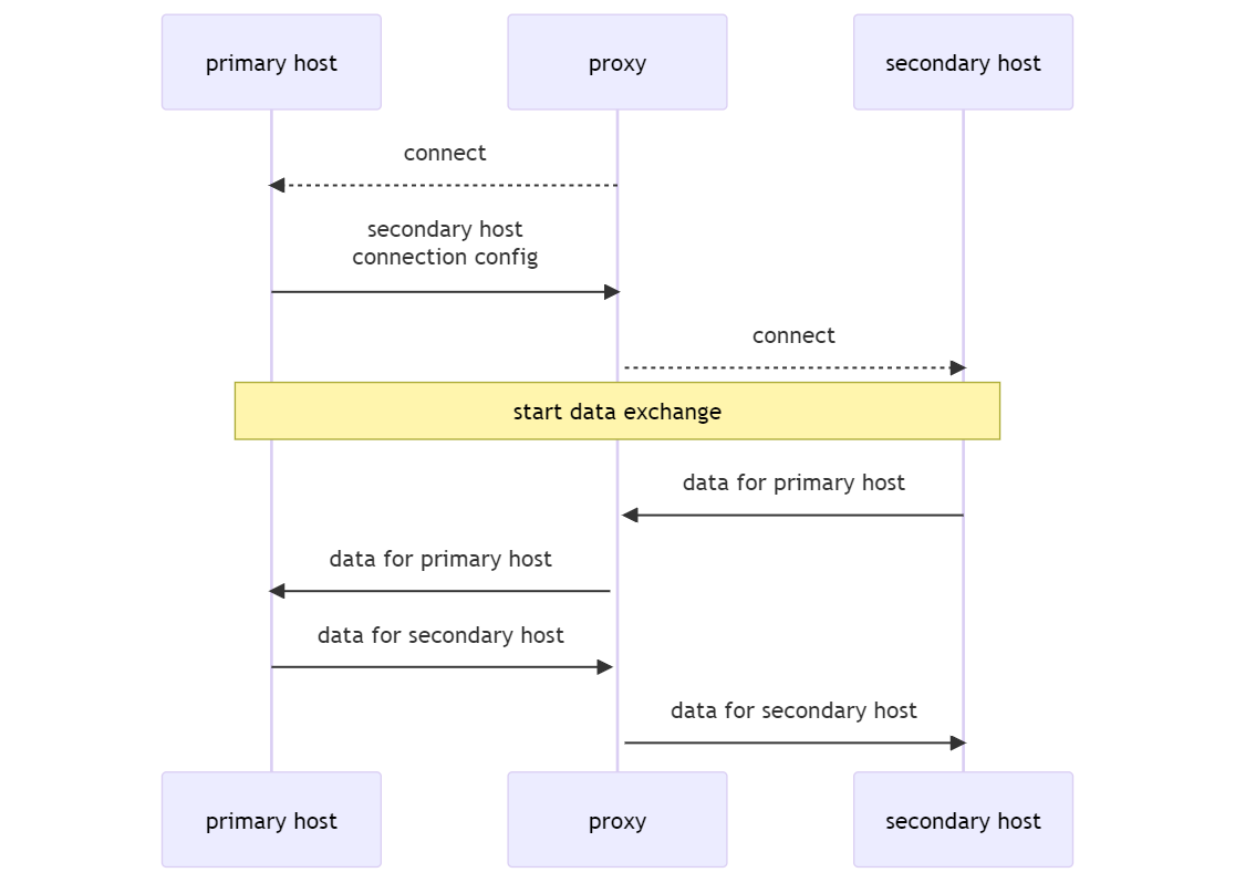
The general workflow of the relay node (called “client” in this context) is as follows:
- The client connects to the first (primary) host using the configuration string specified in the parameters.
- Then the client waits for the command to establish a second connection with another (secondary) host. The configuration of the connection with the secondary host is defined directly in the command parameters.
- After establishing a connection, the primary host and the secondary host exchange data that is relayed by the client.
This process can be illustrated as follows:
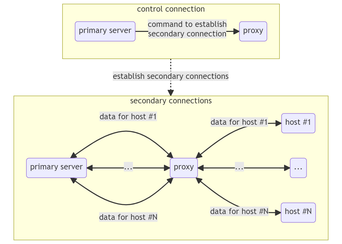
With the proper server implementation, this functionality lets you set up data exchange between the backdoor and an operator—for example, following the scheme below by connecting to the auth server through a relay node:

Also, with the proper implementation of primary server functionality, this scenario can also be used to build flexible routes for transmitting data between the backdoor and an operator, as any backdoor instance with the Bridge module can function as a relay node and an auth server (this module was enabled by default in all analyzed samples). Please note that we do not have access to an actual instance of the primary server, so the example above illustrates only one of the potential use scenarios for the described functionality.
In Mode 1, the command connectCommand for establishing a connection with the secondary host has a size of 16 bytes and must meet the following conditions:
- connectCommand[0] == 501
- connectCommand[1] ^ connectCommand[1] ^ connectCommand[2] == 0
The command connectCommand is examined here as an array of 4 unsigned DWORDs. After receiving this command, the client creates a new, separate connection with the primary host, from which it receives the connection configuration string for connecting to the secondary host. After connecting, the client sends to the primary host a 4-byte status code indicating the progress of this operation. A status code of 0 is sent if the connection was successfully created, otherwise the appropriate error code is sent. Then the primary and secondary hosts proceed to exchange data.
In contrast to Mode 1, Mode 2 does not create a separate connection for data exchange between the primary and secondary hosts. Instead, the commands to connect to new hosts and the data sent to already connected secondary hosts are transmitted over the same control connection. This requires additional headers to be added to data transmitted over the control connection to distinguish their recipients.
The differences between Mode 1 and Mode 2 are illustrated below:
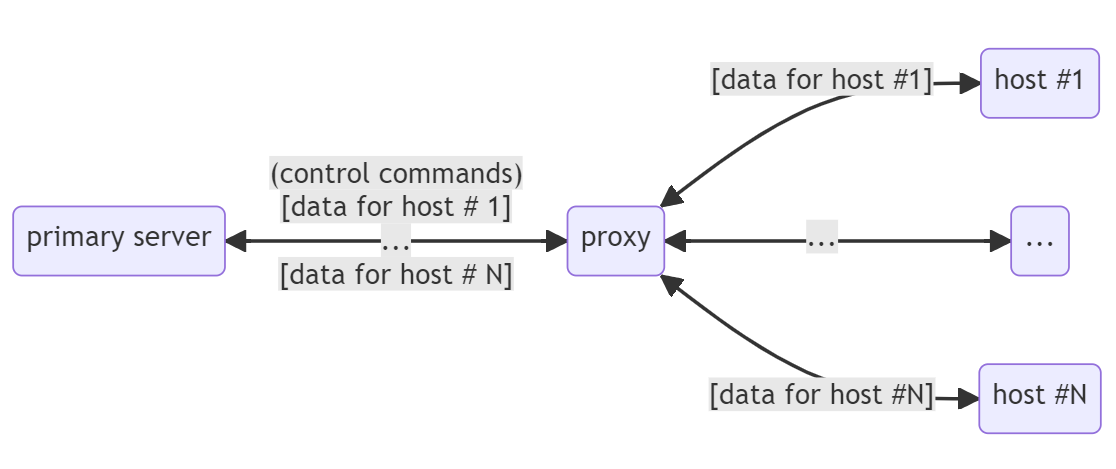
The additional header of the buffer transmitted from the primary server to the client has the following format:
typedef struct
{
    int dataSize;     //  Size of transmitted data
    int connectionID; //  Connection identifier
    int state;        //  Connection state
    char data[]       //  Data
} BRIDGED_CONTROL_CONNECTION_DATA_HEADER;
Data from the client to the secondary host is then transmitted as is, without this header. When transmitting data within an already established connection, the value of the header state field is set to BRIDGED_PACKET_DATA_TRANSMISSION = 0×0. If a data transfer error occurs, the control connection is sent an empty buffer with the header state field set to BRIDGE_CONNECTION_ERROR = 0×4 and connectionID containing the identifier of the corresponding connection.
To establish a new connection, the primary server sends the client a buffer containing the configuration string of the new secondary connection with state = BRIDGED_PACKET_ESTABLISH_NEW_CONNECTION=0×1 and the identifier of the new connection (connectionID). The identifier connectionID is generated by the primary server. After successfully establishing a secondary connection, the client sends the primary server an empty buffer with state = BRIDGED_PACKET_CONNECTION_ESTABLISHED (0×2) and the corresponding connectionID. If the connection is unsuccessful, an empty buffer with state = BRIDGED_PACKET_ERROR is sent.
Command with ID = 502
This command implements an auth server (see the description of the client, agent, auth, and control transports) created in a separate thread. The command takes a serialized string containing the configuration of the server connection (serialization key = 0xC01FA) as a parameter.
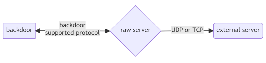
Command with ID = 505
This function creates a separate thread in which a proxy server is started. The proxy server implements its own custom protocol for establishing a connection with the target host. This proxy server may be called a raw proxy because it can operate only on the transport layer, specifically with the tcp transport and the udp transport without establishing a connection (raw mode). Please note that a connection from the client to the proxy can be established using any available transport that is supported by the backdoor. However, the connection from the proxy to the target host can be established only by using the tcp and raw udp transports. Therefore, the raw proxy can be viewed as a kind of gateway for exchanging data with other, external, network hosts.
This command takes the serialized number of the port that must receive the incoming connection (serialization key = 0×201FE) as a parameter. This raw proxy port listens on all available network interfaces.
The procedure for establishing a connection is as follows:
- The client establishes a connection with the raw proxy.
- The client sends a command to connect to the target host. The command has the following format:
typedef struct
{
    unsigned short unused;
    unsigned short dstPort; // Target host port
    in_addr dstAddr;        // Target host IP address
    char configStr[];       // String containing connection configuration elements
} RAW_SERVER_CONNECT_COMMAND;
If dstAddr is not specified (zero), the name of the target host is taken from the configuration string whose length does not exceed 512 bytes. The configuration string has the standard format used by the backdoor. However, only the !proto parameter defining the transport-layer protocol is significant when the string is parsed. If udp is not indicated for this protocol, the connection is established over the TCP protocol. If the configuration string begins with the [ character, the IPv6 version of the corresponding protocol is used. Upon successful connection to the target host, the server sends the code 0×0000000000005A00 to the client and the sides proceed to exchange data. If an error occurs, the code 0×0000000000005B00 is sent.
9. Network subsystem architecture
9.1. Overview of the transport subsystem components
The transport subsystem implemented by the analyzed backdoor is very advanced. The code that implements various components of this subsystem makes up around 70% of the total volume of the backdoor code.
The transport subsystem of the backdoor includes entities known as factories, transport interfaces, transports, and connections. Factories are responsible for instantiating transport interfaces and connections. When the factories are created, they are registered in the orchestrator context, and each of them has its own unique integer ID. In the analyzed backdoor instances, only one factory with the ID 0×01 is used by default.
A transport interface provides all other backdoor components with an interface to do the following:
- Establish outgoing connections (as a client) and receive incoming connections (as a server).
- Receive data from a remote host and send data to it.
- Receive information about the connection state.
- Terminate a connection.
The main purpose of transport interfaces is to conceal the internal hierarchy of transports and the interaction between different levels of this hierarchy.
Each transport is a component (class) that implement a specific network protocol. Transports form a hierarchy amongst themselves. Each transport may be higher, lower, or on the same level as another transport. A higher-level transport always operates over a lower-level transport.
The names of transports are presented below in the same format in which they are encountered in the backdoor code. Please note that the network protocol that is actually implemented by a transport with a specific name may differ from the standard implementation of the protocol with the same name and may have a completely different functionality and properties as will be shown in the section describing the specific transports.
Transports can be divided according to their respective layers of the OSI model:
- Transport layer, providing reliable data transfer between network hosts: tcp, udp, pipe.
- Session layer, providing continuous exchange of information through a set of data transfers between hosts: ssl, http, https, proxy-http.
- Application layer, implementing high-level logic for establishing connections and transmitting data between backdoor instances or between a backdoor and a C2: raw, auth, control, client, agent.
This list of transports can be expanded by installing additional network plugins. The transports listed here are embedded into the backdoor by default.
The reference hierarchy presented here is not actually reflected in the backdoor code but nevertheless provides a convenient overview of the properties of backdoor transports. Despite the fact that named pipes pertain to the session layer of the OSI model and the HTTP and HTTPS protocols pertain to the application layer, the corresponding backdoor transports named pipe, http, https, and proxy-http in this analysis are attributed to other OSI model layers based on their usage context and the properties of the protocol that is actually implemented by the specific network transport.
For example, the pipe transport implemented by the backdoor is used in the code exclusively to ensure reliable data transfer between hosts. Therefore, we attribute this transport to the transport layer of the OSI model within the context of this analysis. The http/https transport implements a protocol that is different from standard HTTP/HTTPS. It operates over the lower-level transports and creates a logical data transfer session that can be resumed if the connection on the transport layer is disrupted. For this reason, and based on its usage context in the backdoor, this transport is attributed to the session layer of the OSI model in our analysis.
A transport does not encapsulate its packets into another transport on the same layer, even though this may be technically possible. Therefore, the tcp transport will not operate over the udp and pipe transports by encapsulating its own packets into these protocols. For example, technically the http transport can operate over the ssl transport. However, a separate session-layer https transport is logically created for this configuration in the backdoor.
Please note that application-layer transports can operate over each other, for example, when a higher-level transport implements or supplements the procedure for establishing a connection to another host. In this case, the packet encapsulation rule mentioned above remains in force.
Each transport can operate as a client or as a server. A transport operates as a server when the method named ListenToConnection is called. This method accepts incoming connection requests from a client.
Unless otherwise specified, for our purposes a connection shall refer to a hierarchy of specific instances of transports that are used to transfer data between backdoor instances and between a backdoor and a C2.
9.2. Creating transport interfaces and connections. Configuring connections
As mentioned earlier, transport interfaces and connections are instantiated by a factory. A transport interface can own only one connection at a time. However, a transport interface can close the current connection and open another connection (instantiated using the factory) based on a previously used or newly created connection configuration.
A connection configuration includes the identifiers of transports that form this connection, and the parameters necessary for their operation (such as the names of hosts, IP addresses, and ports).
The procedure for creating transports must be registered in the factory. In the context of a factory, each transport is identified by its name. However, this does not apply to application-layer transports, which are not registered in the factory but instead are instantiated directly by a transport interface.
The primary way to define the configuration of connections in a backdoor is to use a specifically formatted string that can be described as follows (in extended Backus—Naur form syntax):
ConnectionConfig ::= ConnectionSubConfig {";" , ConnectionSubConfig}
ConnectionSubConfig ::= [SessionProtocolName , "://"], ["["] , HostParameters , ({"|", SessionProtocolParameter} | [TransportProtocolSpecification])
HostParameters ::= Path | (HostName, ":", PortNumber)
SessionProtocolName ::= Identifier
SessionProtocolParameter ::= ("!" , ParameterName, "=", ParameterValue)
TransportProtocolSpecification ::= ("!", "proto", "=", TransportProtocolName)
TransportProtocolName ::= Idenitifier
ParameterName ::= Idenitifier
ParameterValue ::= (Idenitifier) | (Number)
HostName ::= Identifier
PortNumber ::= Number
Identifier ::= (can use all printable ASCII characters except ";" , "|", "://", "!")
Path ::= (standard path in the Windows file system)
More intuitively, the configuration string for a connection with a specified host can be presented as follows:
<name of the session-layer protocol>"://"<host description>"|!proto="<name of the transport-layer protocol>"|"<parameter name>"="<parameter value>..."|!type="<name of the application-layer protocol>
At the beginning, before the “://” string, the name of the session-layer transport is specified, whose creation procedure must be registered in the factory under the corresponding name. For example, this name can be http, https, orssl— see the list above.
After the “://” string, a description of the network host to connect to (or listen to if acting as a server) follows. For example, a URL will be entered for the http transport. If a transport-layer protocol is used for the pipe transport, the name of the pipe will be here; for the udp/tcp transports, the host:port pair will be used.
The !proto parameter defines the name of the transport-layer transport (tcp, udp, or pipe) that the newly created connection will operate over. If this parameter is not specified, the tcp transport is selected by default.
The !type parameter defines the name of the application-layer transport (auth, control, connect, or agent). If it is not specified, the transport type is selected based on the operating context of the interface. For example, the agent transport is used by default in the loop for receiving and processing commands from the C2.
A connection to a specified host may traverse multiple relay nodes. The connection between neighboring hosts in this chain are also defined by a configuration string. The configuration strings for connections of relay nodes are separated from each other by the ; character. Therefore, the configuration of a connection to a destination host via multiple relay nodes generally looks as follows:
<connection to relay node 1>;<connection to relay node 2>; ...
<connection to relay node N>;<connection to the destination host>.
Several examples of connection configurations are presented below:
- “ssl://192.168.1.166:8530|!proto=udp;ssl://igloogawk.com”. This string describes a connection to the C2 server igloogawk.com via the relay node 192.168.1.166. The relay node configuration “ssl://192.168.1.166:8530|!proto=udp” describes a connection using an ssl session-layer transport operating over a udp transport using network host 192.168.1.166:8530 for a remote connection (this string was extracted from a sample configuration and describes the connection to a C2). The destination host configuration “ssl://igloogawk.com” describes a connection using an ssl transport operating over a tcp transport (as mentioned earlier, this transport is selected by default when no transport is explicitly specified).
- “raw://192.168.1.166:2212|!proto=udp|!udp_type=raw”. This string describes a connection to the server 192.168.1.166:2212 (also used as a C2, or more specifically as a relay node to it). The selected session-layer transport is the raw pseudoprotocol, which is not registered in the factory and does not have a separate component (class) for its implementation. Use of the reserved word raw as the name of the session-layer transport means that this connection uses only the transport layer for data transfer. In other words, raw is an empty session-layer protocol. The lower-level transport here is udp. The configuration includes an additional parameter named udp_type whose raw value indicates that the configuration will use a udp transport version that does not provide support for sessions, reliable delivery or correctly ordered data assembly. For more details, see the description of the udp transport.
9.3. Specific transports
Functions of the transport interface have the prototypes presented below:
void CloseConnection(TRANSPORT *this);
StatusCode ConnectToServer(TRANSPORT *this);
StatusCode SendBuf(TRANSPORT *this, const char *buffer, int bufLen);
StatusCode RecvBuf(TRANSPORT *this, const char *buffer, int bufCapacity);
BOOL IsConnectionEstablished(TRANSPORT *this);
StatusCode ListenToConnection(TRANSPORT *this);
StatusCode AcceptConnection(TRANSPORT *this, TRANSPORT **acceptedConnection);
char * GetPeerNameString(TRANSPORT *this);
u_short GetPeerAddressData(TRANSPORT *this);
__int64 GetTransportDescriptor(TRANSPORT *this);
StatusCode SendSessionControlCmd(TRANSPORT *this, int cmd, const char *cmdArgs, unsigned int cmdArgsSize);
StatusCode RecvSessionControlCmd(TRANSPORT *this, int *cmd, const char *cmdArgsBuf, unsigned int cmdArgsBufCapacity);
The transport interface includes the standard functionality:
- Establish a connection with a server (ConnectToServer).
- Receive incoming connections from clients (ListenToConnection, AcceptConnection).
- Send and receive data (SendBuf, RecvBuf).
- Receive connection status information, and information about the remote host of the connection (IsConnectionEstablished, GetPeerNameString, GetPeerAddressData).
There are uncommon functions as well, such as the following:
- Get the transport descriptor (GetTransportDescriptor).
- Send and receive session control commands (SendSessionControlCmd, RecvSessionControlCmd).
Let’s take a closer look at the uncommon elements of the transport interface. The transport descriptor is a 64-bit integer. In particular, for a connection over the pipe transport, this will be the HANDLE of the named channel, and for connections over the udp and tcp transports, the descriptor of the corresponding socket.
This abstraction is introduced to provide uniform polling of the connection array for incoming data or readiness to send data. This uses an extended version of the int WSAAPI WSAPoll(LPWSAPOLLFD fdArray, ULONG fds, INT timeout) function, which differs from the original through its ability to uniformly poll both sockets and pipes—both anonymous and named—in the current implementation of the backdoor. The transport system of the backdoor uses only non-blocking sockets and pipes.
The polling function is registered in a factory. The set of descriptor types to process can thus be extended by creating a new factory and registering the appropriate polling function in it.
The aforementioned functions for sending and receiving session commands (SendSessionControlCmd, RecvSessionControlCmd) are only used by application-layer transports to exchange service commands when initiating a connection.
TCP
This transport belongs to the transport layer. It is used by default if the connection configuration does not explicitly specify the transport level.
The transport is implemented on top of IPv4 (configuration name tcp) and IPv6 (configuration name tcp6). The IPv6 protocol is also used if the configuration string separates the name of the session-layer protocol from the host parameters with the character sequence “://[“, as, for example, in ssl://[igloogawk.com
The core transport functions essentially constitute a wrapper for the Winsock API, as the entire scope of network operations is implemented inside that library.
The configuration may additionally contain bind_ip parameter: the local address with which to associate the socket used in the transport.
UDP
According to the hierarchy provided in the “Overview of the transport subsystem components” section, udp belongs to the transport layer, which implies reliable transfer of data between hosts.
This is a case where the transport name, udp, does not reflect the properties of the actual protocol implementation, something we will examine below. Here’s an example of a connection configuration that uses this transport:
raw://192.168.1.166:2212|!proto=udp|!udp_type=raw
The transport in question can function in one of two modes:
- Raw UDP, where data is sent inside basic UDP datagrams with no extra logic overlaid. The udp_type=raw parameter in the connection configuration corresponds to that mode.
- Connection-oriented protocol over the UDP that ensures a connection between hosts, reliable delivery of packets and integrity of transferred data, which makes it somewhat similar to the TCP. A cursory comparison with analogous protocols that work on top of the UDP shows a certain vague similarity with SCTP and RUDP protocols. All in all, this is a full-featured custom protocol that provides reliable data transmission between hosts.
Further description of the UDP transport protocol will assume the connection-oriented mode by default.
The UDP is logically divided into a connection handler and interfaces, with a one-to-many relationship between these. The connection handler is executed in a separate thread, which is created, always in a single copy for each backdoor instance, as long as there is at least one active connection on top of the UDP transport.
The connection handler implements all of the protocol logic. Its functions include the following:
- Polling transport descriptors for incoming data or readiness to send data.
- Generating and supporting a list of active connections—this is a global list for a backdoor instance.
- Generating outgoing packets and parsing incoming ones.
- Initiating and terminating connections.
- Ensuring that incoming data is correctly assembled.
Data sharing between the transport interface and connection handler relies on anonymous pipes initialized when a connection is set up. Thus, for example, from an interface standpoint, sending data means simply writing it to the appropriate pipe:
int __fastcall UdpTransport::SendBuf(UDP_TRANSPORT *this, const char *dataToSend, DWORD dataLen)
{
  if ( this->connectionState == UDP_CONNECTION_ESTABLISHED )
    return WritePipe(this->sendPipeInterfaceEndpoint, dataToSend, dataLen);
  else
    return ERR_NOT_CONNECTED;
}
The connection handler, which implements all of the data-sending logic, receives the above data. Data reception is similar to that: the interface simply reads the data from the appropriate pipe, where it was written by the connection handler after accepting and processing:
int __fastcall UdpTransport::RecvBuf(UDP_TRANSPORT *this, char *buf, DWORD bufCapacity)
{
  if ( this->connectionState >= UDP_CONNECTION_ESTABLISHED )
    return ReadDataFromPipe(this->recvPipeTransportEndpoint, buf, bufCapacity);
  else
    return ERR_NOT_CONNECTED;
}
The method above is used both for data being sent or received and service messages about connection status. If the transport is running in server mode, pointers to newly accepted connections are transmitted in a similar way:
int __fastcall UdpTransport::AcceptConnection(UDP_TRANSPORT *this, UDP_TRANSPORT **acceptedConnectionPtr)
{
  int readPipe;
  int status;
  UDP_TRANSPORT *acceptedConnection;

  readPipe = this->recvPipeInterfaceEndpoint;
  acceptedConnectionPtr = 0i64;
  status = ReadDataFromPipe(readPipe, &acceptedConnectionPtr, 8u);
  if ( !status )
    status = ERR_NETWORK_DATA_TRUNCATED;
  if ( acceptedConnection )
    *acceptedConnectionPtr = acceptedConnection;
  return status;
}
Packet format
A packet consists of a header and data. The header has the following format:
[data size (2 bytes)][connection identifier (stream id, 4 bytes)][number within the sequence (sequence number, 4 bytes)][flags (1 byte)][data]
The purpose of a packet is defined by flags, of which there are four:
- UDP_SYN = 1: establishing connection
- UDP_ACK = 2: confirmation
- UDP_FIN = 4: connection termination
- UDP_DEMAND_CHUNK = 8: packet request
We explain more about how these are used below.
The connection identifier (stream id) allows the host to tell which connection a packet it received belongs to.
The sequence number (sequence number) defines the order of assembling packets into one buffer upon receiving.
Initiating and terminating a connection
Initiating a connection is a two-step process:
- To initiate a connection, the client sends the server a message with a UDP_SYN flag and a client_stream_id in the message packet body.
- The server responds with a message with UDP_SYN|UDP_ACK flags and a server_stream_id.
The client_stream_id and server_stream_id each have a size of 4 bytes, and they are generated by the host randomly. Generated identifiers are guaranteed not to match the identifiers of other UDP connections within the same backdoor instance. The purpose of these identifiers is to define the UDP transport connection that the packet belongs to.
To terminate the connection, the host sends the recipient a UDP_FIN packet and closes the connection.
Data transmission
Data is transmitted in packets of up to 1460 bytes including the packet header. This data size was probably selected to ensure that a total packet size never exceeded the Ethernet MTU.
A data packet has no flags. Upon receiving a data packet, the host sends the recipient a UDP_ACK packet with the sequence number of the received packet. Received packets are collected into a single buffer according to their sequence numbers and forwarded to the interface.
Lost packets are requested again as follows:
- For each connection, the system stores the sequence number of the next packet that must be sent to the interface. Let’s assume that number is N.
- Suppose the host receives a packet with the sequence number N+m, but the previous packets with numbers N+1, … N+m-1 have not been received yet. In that case, the host requests that the missing packets be resent by sending UDP_DEMAND_CHUNK packets with sequence numbers N+1, …, N+m-1. This is done for each packet that arrives out of sequence. Therefore, UDP_DEMAND_CHUNK packets for the same sequence number may be sent multiple times.
- If the packet thus requested is received, the host sends a UDP_DEMAND_CHUNK|UDP_ACK confirmation with the sequence number of the received packet.
Considering that UDP_DEMAND_CHUNK packets may be sent multiple times, the host waits before resending the requested packet. It starts counting the requests and only resends when the number reaches 32, whereupon the counter is reset.
PIPE
It belongs to the transport layer according to the hierarchy provided in the “Overview of the transport subsystem components” section. It is registered in a factory under the name pipe. This transport is implemented on top of Windows named channels. Here’s an example configuration of a connection that uses this transport: raw://name_of_the_pipe|!proto=pipe
This transport wraps around the functions for working with WinAPI named channels.
In particular, establishing a connection (ConnectToServer) is done with the help of the CreateFileA API; receiving and processing incoming connections (ListenToConnection, AcceptConnection)—with the help of the CreateNamedPipeA and ConnectNamedPipe functions; data receiving and sending—with the help of the ReadFile and WriteFile API calls. Below is an example of the ListenToConnection function used by this transport:
__int64 __fastcall PipeTransport::ListenToConnection(PIPE_TRANSPORT *this)
{
  __int64 result;
  unsigned int v3;
  int hDataPipe;
  HANDLE EventA;
  PIPE_TRANSPORT *i;

  this->isServer = 1;
  result = CreatePipeNoBlockingMode(&this->hControlPipeRead, &this->hControlPipeWrite, 0i64, 0);
  v3 = result;
  if ( (int)result < 0 )
    return result;
  hDataPipe = (unsigned int)CreateNamedPipeA(
                              this->transportPipePath,
                              0x40080003u,
                              0,
                              0xFFu,
                              0x100000u,
                              0x100000u,
                              0,
                              0i64);
  if ( hDataPipe < 0 )
    return -GetLastError();
  EventA = CreateEventA(0i64, 1, 0, 0i64);
  this->pipeOverlapped.hEvent = EventA;
  if ( !EventA )
    return -GetLastError();
  this->hDataPipeInstance = hDataPipe;
  if ( !ConnectNamedPipe(hDataPipe, &this->pipeOverlapped) )
  {
    result = -GetLastError();
    if ( result != -ERROR_IO_PENDING && result != -ERROR_PIPE_CONNECTED )
      return result;
    v3 = 0;
  }
  if ( PipeTransport::ActiveConnectionsList )
  {
    this->next = PipeTransport::ActiveConnectionsList;
    for ( i = PipeTransport::ActiveConnectionsList; i->next; this->next = i )
      i = i->next;
    i->next = this;
  }
  else
  {
    PipeTransport::ActiveConnectionsList = this;
  }
  this->next = 0i64;
  if ( !PipeTransport::ConnectionsListHead
    && !CreateThread(0i64, 0i64, (LPTHREAD_START_ROUTINE)PipeTransport::CleanupInactiveConnections, 0i64, 0, 0i64) )
  {
    return -GetLastError();
  }
  return v3;
}
In server mode, all incoming connections created by pipe transports are placed in a single global (within the backdoor instance) list of active connections (PipeTransport::ActiveConnectionsList in the above example). A separately created thread goes through the list every 100 seconds, closing every active connection (PipeTransport::CleanupInactiveConnections in the above list).
Note that adding connections to and removing from PipeTransport::ActiveConnectionsList is done without any synchronization primitives (such as critical sections or mutexes) despite the fact that the list may be accessed by several threads.
This transport probably serves as an option for communication between logically isolated network segments and a C2 (through a relay node) for when transmission of data (commands) via the usual protocols is problematic.
SSL
This transport belongs to the session layer according to the hierarchy provided in the “Overview of the transport subsystem components” section and implements the SSL protocol. It is registered in a factory as ssl or ssl3.
Similarly to the TCP transport, it wraps around the functions of the WolfSSL library statically linked to the examined sample. This library implements the entire scope of operations involved in initiating/terminating connections and sending/receiving data.
A version of the transport named ssl implements TLS version 1.3, and the ssl3 version implements SSL version 3.
Server certificate is not verified when a connection is initiated.
HTTP (HTTPS)
This is a session transport in this backdoor’s terms. It works on top of the underlying (transport-layer) transport, whose job is to ensure reliable data transmission between hosts. Note that this transport does not follow the HTTP specification.
The HTTP transport is implemented in the form of two logical components:
- Interface
- Separate thread that sends and receives data
The interface interacts with the thread through a series of anonymous pipes. For example, when calling the interface method SendBuf(TRANSPORT *this, char *buf, DWORD bufLen) for sending data, the data to be sent is simply written to the appropriate pipe, while the thread handles all the work of sending and receiving data across the network.
Only one copy of the thread is created every time. It processes every existing HTTP transport connection, each of which is registered globally as part of the backdoor process.
The main transport parameters (host, url, protocol version, and additional headers) are defined in the transport configuration string.
A connection is established as follows:
- The client sends a POST request to the url specified in the config.
- When the server accepts the connection, it sends the response, “HTTP/200″, in contrast to the standard success response, “HTTP/200 OK”. It is worth noting that the protocol uses the Content-Length header in a non-standard way. Unlike the standard HTTP, where this header contains the message body length (the part following the headers and double CRLF), in this protocol, Content-Length contains the length of the entire HTTP packet including the headers and message body. The body of each of the above requests/responses contains an extra header formatted as follows:
struct HttpChunkHeader
{
    char encodeKey;      // Key used to encrypt the header
    DWORD dataSize;      // Size of the data that follows the header
    QWORD connectionId;  // Connection identifier
    char checkSum;       // Checksum
}
The checkSum is calculated as a byte sum modulo 2 (XOR) of the entire preceding part of the header. After calculating the checksum, all the packet headers and data, with the exception of encodeKey, are encoded with the single-byte XOR cipher using the encodeKey. No data is sent with these headers, although the format allows it. The purpose of exchanging headers when initiating a connection is to communicate to the client the server-generated identifier of the new connection, connectionId.
After a connection is established, the hosts exchange data. The data is transmitted unchanged, with no added HTTP headers or transformations.
The transport can run in two modes:
- “Connection: keep-alive” leaves the transport connection open after sending/receiving all of the data.
- “Connection: close” closes the connection every time after all of the data is sent/received. The choice of mode depends on the headers in the connection requests.
The protocol provides an option to resume the transport connection if there are transport-layer connection errors. So, if there was a client-side transport error, it reconnects to the server, sending the appropriate connectionId of the interrupted connection in the request header (HttpChunkHeader).
The HTTPS transport is the above http transport running on top of the SSL transport.
PROXY-HTTP (PROXY-HTTPS)
This transport wraps around the HTTP/HTTPS transport, adding a HTTP proxy connection feature that supports authentication. The transport supports two authentication methods: Basic and NTLM.
When connecting to an HTTP proxy, the client first tries the Basic authentication method. Failing that, it attempts to get authenticated with NTLM.
9.4. Application-layer transports
As mentioned above, protocols in this application layer run on top of the session-layer transports. Unlike the lower-layer protocols, the functions for creating these transports are not registered in a factory but instantiated directly by the transport interface when creating a new connection. So, the backdoor has a rigidly defined set of application-layer transports that cannot be extended with a system of network plugins.
The backdoor sample we are analyzing contains four application-layer transports: auth, control, client, and agent. In transport configuration, the application-layer protocol is defined by the value of the !type parameter: ssl://igloogawk.com|!type=auth. Application-layer transport may also be defined using the keyword raw, which signifies that the connection uses no protocols belonging to the layer in question and sends raw data.
The control, client, and agent transports run on top of the auth transport. Let’s take a closer look at each.
AUTH
The main function of this transport is to provide a mechanism for sending session control commands to the application-layer protocols above it. To implement this, the auth transport defines the SendSessionControlCmd and RecvSessionControlCmd methods, and implements a connection procedure of its own by redefining the EstablishConnection method. The backdoor samples we studied have no other transports apart from auth that provide session control on the application level.
This transport uses two connection modes: direct and relay. It implements the following protocol when connecting directly:
- The client connects to the server on the transport and session levels.
- The client sends the server a COMMAND_CONNECT command (code = 0×00) without arguments.
- If the server responds with a COMMAND_CONNECT_RESPONSE command (code = 0×01) without arguments, the connection is considered to be established.
- If the server responds to the client with a COMMAND_RECONNECT command (code = 0×08), the connection procedure restarts at Step 1.
Here’s a diagram of the process:
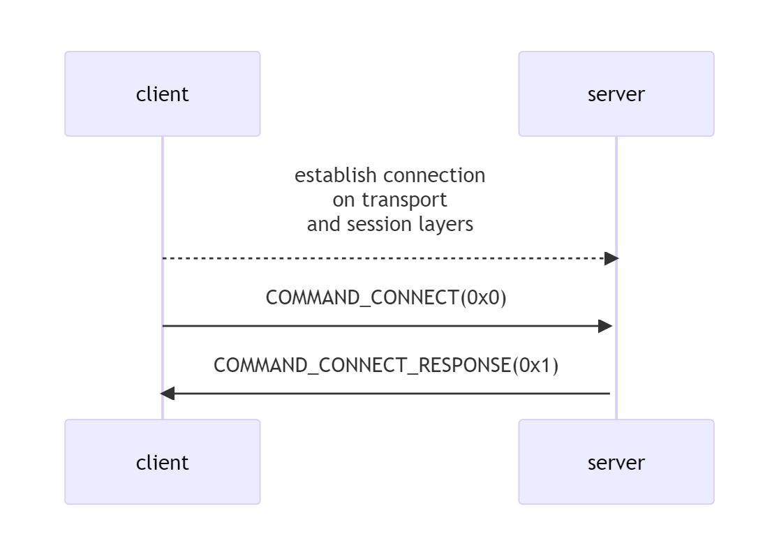
In the above description and the descriptions of the other application-layer transports, all commands are sent/received with the help of the SendSessionControlCmd/RecvSessionControlCmd methods.
A connection through a relay node (referred to as “proxy” going forward) is established as follows:
- The client connects to the proxy on the transport and session levels.
- The client sends the proxy a COMMAND_CONNECT_TO_PEER command (code = 0×02), providing a configuration string for a connection to the next intermediate or final network route point as an argument.
- The proxy establishes a direct connection to the next point if it’s the final point or uses the protocol we are describing if it’s another relay node.
- Upon connecting to the relay node, the proxy sends the client a COMMAND_CONNECTION_ESTABLISHED command (code = 0×06) without arguments. The connection is then considered to be established, and data transmissions begins.
Here’s a diagram of this protocol:
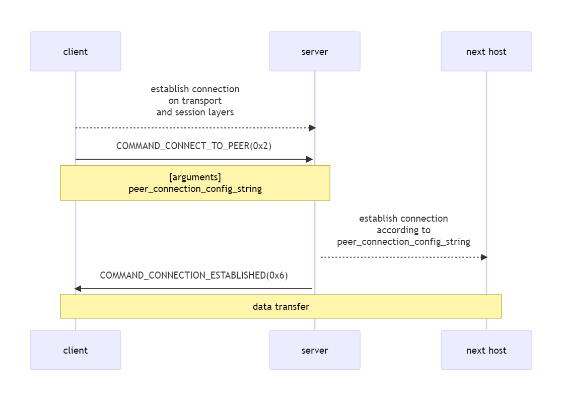
Commands in this transport are sent in the following format:
typedef struct
{
    char key;
    char commandValueDecodingTableId;
    char encodedCommand;
    int  argumentSize;
    char headerCheckSum;
    char argumentData[];
} COMMAND_PACKET;
The argumentSize field is converted to big-endian when the packet is generated. Other header elements are not modified during packet generation. Also when a packet is generated, the system calculates a headerCheckSum value as a byte sum modulo 2 (XOR) of the commandDecodingTableId, encodedCommand, and argumentSize fields. This sum is checked when the command is received.
After the checksum is calculated, each byte of the generated packet including its headers and data is XORed with the key value. The key is randomly generated during packet generation. The key is guaranteed to be non-zero.
Command codes are not transmitted explicitly. They are encoded using a substitution table that must be the same for the client, server, and every relay node. encodedCommand is the command value after encoding with the table in question. commandValueDecodingTableId is the identifier of the table among all tables of this type in the backdoor. Although there can be several substitution tables used by various transports, the samples under review use just one, with the number 1, shown below:
char commandEncodingTable = [0x24, 0x64, 0x13, 0xA4, 0xB2, 0x2C, 0x4F, 0x9F, 0xAF];
AGENT/CLIENT
The agent and client transports are used as the main application-layer transport when setting up a connection with the C2. Establishing a connection with the help of these transport requires an extra host that we will designate as the auth server. This is not a name used in any of the samples—we introduce it here for convenience. We will designate the hosts connected by the above transports as Host 1 and Host 2. The agent and client transports are paired transports in the sense that if Host 1 is connected to the auth server through agent, the Host 2 may be connected to the auth server only through the client transport, and vice versa.
The connection that the backdoor instance uses to receive commands to execute has the agent type. The usage context suggests that the connection used by the backdoor operator to send commands to the auth server for the backdoor to execute has the client type.
A possible interaction pattern is presented in the diagram below:
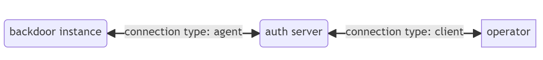
Each backdoor sample is capable of functioning as an auth server, which enables it to use virtually any running backdoor instance (such as previously infected machines on the target network or compromised servers on the Internet) as a C2 as long as the operator can connect to the host with the backdoor as the client. A logical connection between the infected host and the backdoor operator is created, which may be relayed through numerous compromised hosts.
The auth server accepts a new agent connection on the lower transport levels and establishes a connection via the auth transport protocol, with the agent and client running on top of it. This uses the connection option without a relay node (see the description of the auth transport). After that, the system searches for a suitable free client connection. If none is available, the new connection remains in standby. If a suitable client connection is available or appears, the auth server mediates a session between that and the newly accepted connection. This is followed by transmission of data, which the auth server also mediates. The above is true for a new client connection, too. Two connections, auth and client, that are free (in standby mode) are considered suitable if both have the client authenticity validation flag set or neither does. This parameter, NEED_TO_ENSURE_CLIENT_AUTHENCITY, is set in the transport configuration (serialization key = 0×30047).
Let’s take a closer look at the protocol for connections between the agent and client hosts.
As mentioned above, the auth server mediates a session between the client and agent hosts, which they use to exchange data. The data is encrypted with an RC4 session key that the parties generate while connecting. The parties agree on a session key using the elliptic-curve Diffie—Hellman ephemeral (ECDHE) protocol. The encryption helps to hide the contents of transmitted data from the auth server.
The session initiation protocols differ depending on the aforementioned NEED_TO_ENSURE_CLIENT_AUTHENCITY (key = 0x30047) parameter. If this parameter is set, the session initiation procedure gets extra steps to authenticate the correspondents, namely to make sure that the connecting parties are not some outside clients not authorized by the backdoor operators.
Let’s take a closer look at the session initiation protocol from the standpoint of a client that implements the agent transport.
- The client initiates a connection with the auth server (referred to as the server in this description) on the transport and session levels.
- The client sends the server a COMMAND_CONNECT_AGENT command (code = 0×3) with a connect request argument, which contains data required for establishing a connection. The connect request contains the following serialized data:
- Ephemeral public key to generate a session key (serialization key = 0x50052)
- Data compression type (serialization key = 0x30051)
- Client authenticity validation flag NEED_TO_ENSURE_CLIENT_AUTHENCITY (serialization key = 0x30047)
- If there is no need to validate authenticity (NEED_TO_ENSURE_CLIENT_AUTHENCITY == 0), the server finds a suitable client, and then sends the agent a COMMAND_CONNECT_CLIENT command (code = 0x4) with a connect response argument. This argument includes the following:
- Connect request message received from the client when initiating a session with the auth server . The message contents are described in item 2. 1;
- String peer info representing the client details (for example, “:”), serialization key 0xC0048. The client is sent a COMMAND_CONNECT_AGENT command with a connect response argument, which includes the same types of components: a connection request and host details. After exchanging the data, the parties agree on a session key, and the connection is considered to be established. Data is exchanged via the server.
- If the authenticity of the parties needs to be validated (NEED_TO_ENSURE_CLIENT_AUTHENCITY == 1), the server sends the agent a COMMAND_RECONNECT, command with a message to sign argument (serialization key = 0x5004F)—a randomly generated 32-byte array.
- The agent calculates the digital signature of the received message by using a digital signature pattern based on the Edwards-curve Digital Signature Algorithm (EdDSA). The private key is defined in the transport configuration (serialization key = 0x50049). Then the agent sends he server another COMMAND_CONNECT_AGENT command with a connect request signed argument, which includes the following:
- Message to sign (serialization key = 0x5004F)
- Its digital signature (serialization key = 0x50050)
- Public key for validating the signature (serialization key = 0x5004E)
- Newly generated ephemeral public key for generating a session key (serialization key = 0x50052)
- Data compression type (serialization key = 0x30051)
- Client authenticity validation flag NEED_TO_ENSURE_CLIENT_AUTHENCITY (serialization key = 0x30047)
- The server validates the message it received, which must satisfy the following conditions:
- The received message to sign must match the sent message.
- The received public key for message validation (serialization key = 0x5004E) must match the public key defined earlier on the server. For the samples under review, this is a hard-coded array: 6E 98 0C 6B 8F 5F 70 5C 27 61 54 05 03 DF 64 C5 FA 28 92 5D 5A 94 6C 21 F7 7F 4F 00 B4 11 E5 A1.
- The digital signature received must be valid. If authentication is successful, a session is initiated as described in item 3. The initiation and authentication procedure for client connections follows the same steps, except that the COMMAND_CONNECT_CLIENT command is sent in place of the COMMAND_CONNECT_AGENT.
Here’s a diagram of this protocol:
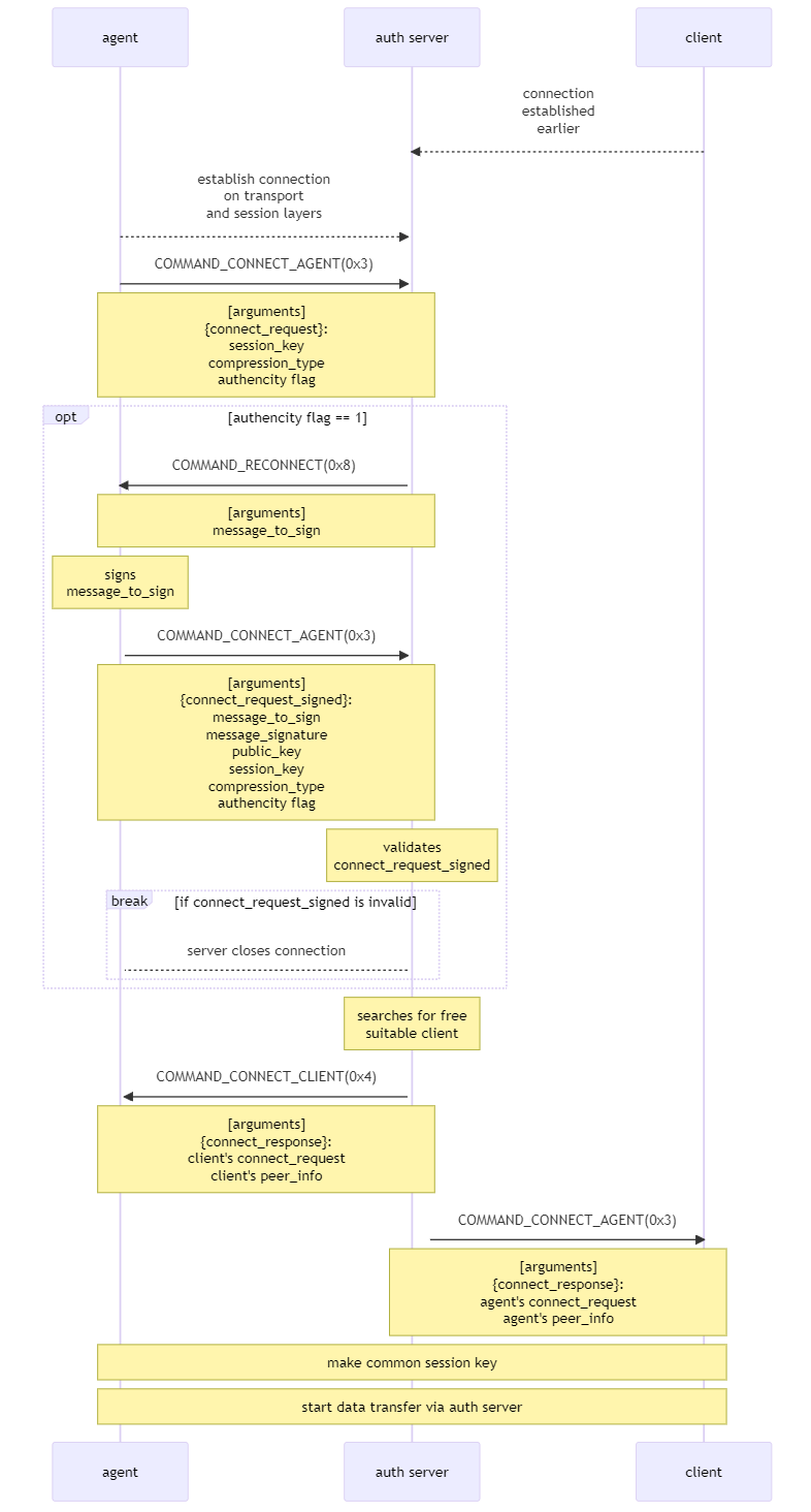
Transmission of data via connections of this type uses buffers preceded by headers of the following format:
<data size, 4 bytes> [<message number seq_num, 4 bytes><uncompressed data size, 4 bytes> <the data itself>]
The message number, uncompressed data size, and the data itself are encrypted with the RC4 session key generated previously as the connection was established. When a party receives a new data buffer, it sends a confirmation in the form of an empty buffer with the following header:
<data size == 4, 4 bytes> [ <message number seq_num, 4 bytes> <number of the buffer reception of which is confirmed, 4 bytes> ]
Every field in the packet save for the first one is encrypted with the session key. Note that data whose receipt was not confirmed will not be resent. The mechanism is used for recording session data transfer statistics, which will be covered below.
Data can be pre-compressed with LZ4 prior to transmission as long as both parties support the algorithm. Available compression modes are defined in the transport configuration (COMPRESSION_TYPE, serialization key = 0×30051), with values from 1 through 3. If the compression mode N is set, the party will support every mode from 1 through N. Parties that exchange data during a session agree on a compression mode with the smallest value available for each of the parties.
In the sample under review, the COMPRESSION_TYPE set to 1 means that data will be transmitted uncompressed. The parameter values 2 or 3 correspond to LZ4. The modes 2 and 3 do not differ in any way.
A buffer transmitted during a session will not be compressed in the following cases:
- The size of a random 256-byte section of the compressed buffer constitutes more than 80% of the uncompressed size.
- The buffer size is less than 256 bytes.
- The buffer could not be compressed.
Both parties to the session record statistics on data they exchange, and the figures thus calculated are serialized in the parties’ connection configurations. The following are calculated:
- Compressed data send rate (COMPRESSED_DATA_SEND_RATE, serialization key = 0x30055)
- Uncompressed data send rate (RAW_DATA_SEND_RATE, serialization key = 0x3004B)
- Compressed data receive rate (COMPRESSED_DATA_RECV_RATE, serialization key = 0x30056)
- Uncompressed data receive rate (RAW_DATA_RECV_RATE, serialization key = 0x3004C)
No functionality we found in the samples under review made use of the above statistics.
CONTROL
The control transport is an auxiliary transport whose function is to receive information about the status of the auth server. The current implementation of the backdoor only supports receiving the number of standby agent connections, separately for those with and without authentication.
A client that uses this transport might be a way for the backdoor operator to trace new agent connections from backdoors and initiating client connections to these.
Each of the samples we studied implements a version of the control transport client, but it does so incompletely, as it only connects to the auth server, without sending any commands to it or receiving any information.
The connection initiation protocol resembles the similar auth and client transport protocols, except that the client is always authenticated when a control connection is initiated. The command codes and argument contents are different as well.
A connection is established as follows:
- The client connects to the server on the lower transport levels.
- The client sends the server a COMMAND_CONNECT_CONTROL command (code = 0×5) with an argument that contains the serialized flag NEED_TO_ENSURE_CLIENT_AUTHENTICITY (0×30047). The meaning of that parameter in the context of this protocol defines which type of connections we want to receive information about: authenticated (flag set to 1) or unauthenticated (flag set to 0).
- As in the case with the message to sign from the agent transport, upon receiving the command, the server generates a random 32-byte message and sends it to the client in serialized form (key = 0×5004F) as an argument for the COMMAND_RECONNECT command (code = 0×8).
- The client signs the message with an EdDSA signature using a private key stored in the transport configuration and sends the server another COMMAND_CONNECT_CONTROL command (0×5), with the following serialized data as arguments:
- Message to sign (serialization key = 0x5004F)
- Its digital signature (serialization key = 0x50050)
- Public key for validating the signature (serialization key = 0x5004E)
- Newly sent parameter NEED_TO_ENSURE_CLIENT_AUTHENTICITY (serialization key = 0x30047)
- The server validates the response it receives according to the criteria listed in the descriptions of the client and agent transports. The public key sent for validation may match either the client and agent connection validation public key, or the second possible key:
char pubKey2 = [0xB8, 0x29, 0x7D, 0xF4, 0x02, 0x42, 0x32, 0xEF, 0x60, 0xA3, 0x80, 0x23, 0x91, 0x4F, 0x5D, 0x12, 0x61, 0x9D, 0xAE, 0xE8, 0x57, 0x10, 0x17, 0xE9, 0xB5, 0xB2, 0x9A, 0x3F, 0xE0, 0xA6, 0x45, 0x0D];
If validation fails, the server closes the connection. If validation is successful, the server sends the client a COMMAND_CONNECTION_ESTABLISHED command (code = 0×6), the connection is considered to be established, and the server proceeds to process commands from the client.
Here’s a diagram of this process:
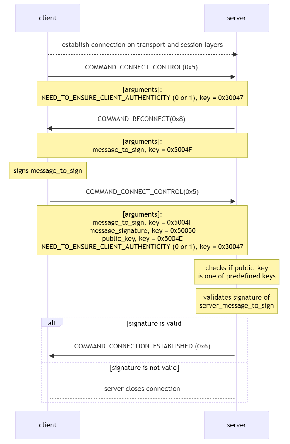
As mentioned above, the client may send only one command to the server: CONTROL_GET_FREE_AGENTS_COUNT (code = 0×4): get the number of free agent connections, with or without the authentication requirement, depending on the value of the NEED_TO_ENSURE_CLIENT_AUTHENTICITY parameter specified when the connection was initiated. This command may have an argument—the serialized value in seconds (key = 0×3004A) of the timeout for waiting for new connections if there are no free ones. The server sends the result of the command execution as an argument for a COMMAND_CONNECTION_ESTABLISHED command (0×06). In the absence of free connections, the server sends the client a COMMAND_CONTROL_NO_DATA command (0×07) without arguments. After a response is sent, the command receiving and processing cycle repeats.
Conclusion
Our analysis suggests that the Dark River group launches one-off attacks on thoroughly selected targets, as evidenced by targeted email campaigns that consider the nature of the target companies’ operations. The attacks are hard to attribute, as for each target, the group deploys a separate network infrastructure unrelated to any other malicious campaigns.
The group’s main tool, the MataDoor backdoor, has a modular architecture, with a complex, thoroughly designed system of network transports and flexible options for communication between the backdoor operator and an infected machine. The code analysis suggests that the developers invested considerable resources into the tool.
Our study shows that Russian defense industry enterprises remain an object of targeted attacks that utilize increasingly complex and sophisticated tools. The Dark River group typifies these activities aimed at espionage and theft of confidential information.
Authors: Denis Kuvshinov and Maxim Andreev, with the participation of the incident response and threat intelligence teams.
Applications
Verdicts by Positive Technologies products
YARA rules
| exploit_win_ZZ_CVE202140444__Exploit__MSHTML__RCE__Artifact |
| tool_win_ZZ_OfficeTemplate__Downloader__Encoding__Artifact |
| apt_win_CN_APT41__Trojan__ExportEngineLoaderString |
Behavioral rules
| Trojan.Win32.Evasion.a |
| Trojan.Win32.Generic.a |
| Trojan.MachineLearning.Generic.a |
| Create.Process.NetworkScanner.NetworkScanning |
| Create.Process.Reg.RegistryModify |
| Create.Process.Regsvr32.RestrictionsBypass |
| Create.Process.Rundll32.RestrictionsBypass |
| Create.Process.Whoami.Reconnaissance |
| Create.Query.WMI.CheckVM |
| Delete.Process.TerminateProcess.Evasion |
| Read.NetShare.RPC.Enumeration |
| Read.Process.Handle.Enumeration |
| Read.Registry.Key.NetAdapterId |
| Read.Registry.Key.NetInterfaces |
| Read.System.Info.Reconnaissance |
| Read.System.RemoteResources.Enumeration |
| Read.File.Name.Enumeration |
Network rules
| BACKDOOR [PTsecurity] Matadoor Magic 10009938 |
| BACKDOOR [PTsecurity] Matadoor Magic 10009939 |
| BACKDOOR [PTsecurity] Matadoor Magic 10009940 |
| BACKDOOR [PTsecurity] Matadoor CnC 10009941 |
| BACKDOOR [PTsecurity] Matadoor 10009946 |
| BACKDOOR [PTsecurity] Possible Matadoor HTTP in UDP Request 10009947 |
| BACKDOOR [PTsecurity] Possible Matadoor HTTP in UDP Response 10009948 |
PT Sandbox
| BACKDOOR [PTsecurity] Possible Matadoor 10009942 |
| BACKDOOR [PTsecurity] Possible Matadoor HTTP in UDP 10009950 |
| BACKDOOR [PTsecurity] Possible Matadoor 10009951 |
| BACKDOOR [PTsecurity] Possible Matadoor Response 10009952 |
| BACKDOOR [PTsecurity] Possible Matadoor Multiple HTTP Request 10009955 |
| BACKDOOR [PTsecurity] Possible Matadoor Multiple HTTP Response 10009956 |
| BACKDOOR [PTsecurity] Possible Matadoor HTTP in UDP 10009959 |
| BACKDOOR [PTsecurity] Possible Matadoor Multiple HTTP in UDP Request 10009960 |
MITRE
| Initial access | ||
| T1566.001 | Phishing: Spearphishing Attachment | The Dark River group uses phishing email campaigns with malicious attachments |
| Execution | ||
| T1059.003 | Command and Scripting Interpreter: Windows Command Shell | The Dark River malware features remote command shell functionality |
| T1106 | Native API | The Dark River malware uses WinAPI functions to run new processes |
| T1129 | Shared Modules | The Dark River malware can download additional modules to execute malicious functions |
| Persistence | ||
| T1543.003 | Create or Modify System Process: Windows Service | The Dark River group creates malicious services to gain persistence on a target host |
| Defense Evasion | ||
| T1622 | Debugger Evasion | Some samples of the Dark River malware are packed with the Themida protection tool, which detects debuggers |
| T1140 | Deobfuscate/Decode Files or Information | MataDoor executables are obfuscated with a protector to hamper detection and analysis |
| T1036.004 | Masquerading: Masquerade Task or Service | MataDoor executable file names imitate the names of legitimate executables deployed on a target host |
| T1112 | Modify Registry | MataDoor stores its configuration in encrypted form inside the registry |
| T1027.002 | Obfuscated Files or Information: Software Packing | Every MataDoor sample contains separate functions shielded by a protector via virtualization |
| T1620 | Reflective Code Loading | MataDoor reflectively loads PE modules with plugins into the address space of its process |
| T1218.010 | System Binary Proxy Execution: Regsvr32 | MataDoor can be started with the help of the Regsvr32 system utility |
| T1218.011 | System Binary Proxy Execution: Rundll32 | MataDoor can be started with the help of the Rundll32 system utility |
| Discovery | ||
| T1083 | File and Directory Discovery | MataDoor can collect information about files and directories on a compromised host |
| T1135 | Network Share Discovery | MataDoor can collect information about shared network resources in a compromised network |
| T1046 | Network Service Discovery | MataDoor can collect information about hosts with predefined open ports |
| T1057 | Process Discovery | MataDoor can collect information about processes running on an infected host |
| T1018 | Remote System Discovery | MataDoor can collect information about the availability of hosts in a compromised network |
| T1082 | System Information Discovery | MataDoor can collect information about the OS version and the computer name of a local machine |
| T1016 | System Network Configuration Discovery | MataDoor can collect information about the IP and MAC addresses of the local network interface of a compromised host |
| T1049 | System Network Connections Discovery | MataDoor can collect information about active TCP connections on a compromised host |
| T1033 | System Owner/User Discovery | MataDoor obtains and sends to the C2 the name of the current user of the compromised host |
| T1124 | System Time Discovery | MataDoor can collect information about the system time on an infected host |
| Collection | ||
| T1560.002 | Archive Collected Data: Archive via Library | MataDoor can compress collected data with a statically linked zlib library |
| T1074.001 | Data Staged: Local Data Staging | MataDoor can save intermediate data collection results locally to send to the C2 later |
| T1005 | Data from Local System | MataDoor can harvest data from an infected host |
| Command and control | ||
| T1071 | Application Layer Protocol | MataDoor malware can use application-layer protocols, such as SMB, and an HTTP-like custom protocol to communicate with the C2 |
| T1132 | Data Encoding: Standard Encoding | MataDoor can compress the data it sends over networks with LZ4 |
| T1572.001 | Encrypted Channel: Symmetric cryptography | MataDoor encrypts traffic with RC4 |
| T1572.002 | Encrypted Channel: Asymmetric cryptography | MataDoor contains a statically linked WolfSSL library for encrypting traffic |
| T1008 | Fallback Channels | MataDoor can use alternative configurations to connect to the C2 |
| T1095 | Non-Application Layer Protocol | MataDoor can connect on top of the TCP protocol and via a custom protocol based on UDP datagrams |
| T1571 | Non-Standard Port | MataDoor can connect to the C2 on ports that are not typical of the protocol being used |
| T1572 | Protocol Tunneling | MataDoor builds a hierarchical system of protocols, where a lower layer encapsulates a higher one, thus tunneling the traffic |
| T1090.001 | Proxy: Internal Proxy | MataDoor can set up a channel to the C2 through a proxy located on a compromised network |
| T1090.002 | Proxy: External Proxy | MataDoor can set up a channel to the C2 through a proxy located on an external network |
| T1090.003 | Proxy: Multi-hop Proxy | MataDoor can set up a channel to the C2 through a chain of relay nodes |
| Exfiltration | ||
| T1030 | Data Transfer Size Limits | MataDoor can divide data it sends into chunks of variable size |
| T1041 | Exfiltration Over C2 Channel | MataDoor can send data over an existing C2 communication channel |
IOCs
File indicators
Loader service
| sha256 | sha1 | md5 |
| 2019322c33b648c9d3f7c8a17a990860044c03ed7bd2fc9e82139c22e9bc5635 | 3d4c3856f86c1dac1fe644babe87f1e5b6c6636f | 1f19f7db272cc5ec22eb08987aaffcab |
| 207f386ebeb29e64e6b7fd10929217e1a664f06e6cc503e8798f57e0af2e5267 | 3f8016bafb700595490b732b92f8501201f0c9af | 01f3a22bf3e409154e79e067370ed98a |
| 2ba653faef17d9ea623be1138f6f420be27c95d8ad7ee1ea0d15ae718895176d | bf8f0b845c8f13b4386b7204add3c5d2e504b4c6 | 4d1e16e2b914243e0c63017676956a73 |
| 748b9e94dc62e1fa364e9daec7d4bbb94a69b304cb81e1a1b6d302be47381a94 | 9cc89d708fcc2b114f6589d8077f66395d4b68ba | fd7de2b8572f35f0f6f58bba6ff2360e |
| 9b632505c27fa8ee58f680599fcc0b1794439af17a8c95df9f413e227e34798c | 8a3d32cb67bbf600c81577f4c2dd0a5e601c43d4 | 538505d57722f6f6e747f7f1517f9c7d |
| b822db93cde13ee2b2faf41e5a6096782bda7a71ef028641d2ce6ad9db777b67 | d3d38d113fcaf3ea2e1b8bc5c32182141f918246 | b52439640b7f0e0273f0d15bb3af6198 |
| c8399484d20c0ebed376cc8147e003cf4d930b5130392ae0e14cee0cec42d484 | 6da222a04b4d0ad74f7ab186d235b55a9bcf7a18 | cc26e5fda0083f750d7748eeaea45350 |
| ec70414b2295392cf7200b99747922a5648c4d2882140bd04c7661030aabe928 | ae0bf4a92b37da3ca4dbd965bc646a747b7ceaf4 | 317f1027095bc41de8fbcfce2c764ac4 |
MataDoor
| sha256 | sha1 | md5 |
| 0085a02b9ba24afd266116df43acbd4f57fc8822af4929e7d17b59f2ceae9418 | 9320a614916bbfaa31853d785ffe0ed0fc7b54f4 | 79fc7ed090bc935881e7c242e40071a2 |
| 3c1cfc2b8b7e5c2d713ec5f329aa58a6b56a08240199761ba6da91e719d30705 | 87e3e59f6653ae1306461bf9683bda92f442d77f | fe93382464347be4361c7e8fb131a668 |
| 566835ce413271ddca8d5014c912dda8ba7e5e45573a7da6ba8e20d72541a2ca | 73d6694a0339cc4083f66395b6b4b3da324e2113 | 6f736eac915c2b647bfbba9e5dccf0cb |
| 660bfbeeaf674e4e95c43bb61d7d0aec88154527e1218e51c1cb75d77c8acdda | 6251126c3a44d5f8a72f0790ae8aba1b195cb5b2 | 610303b58eb5d039c15061e48b743d17 |
| ec1205a050693f750dd6a984b68eb2533539a34a5602744127d1b729b22f42fd | 73055a139a248cccb2b6f4360f072f7626b4ce7c | 20ee5ab5724339f16c19be92d0912bb6 |
| fdf50a01a8837c9f4280f3e7f7e336f3cbf93a30c78b48aa50c05b45a7f2ee5b | 4a65848af705b2d2b23af0b0795f0ec8bfdc0c69 | 34e3e94f9955c101640b44926bc44393 |
Phishing documents
| sha256 | sha1 | md5 |
| 0b06fb7f53bb7963ec2ff89d832b831763706e44d206a4d0a8c813ebee633e22 | f463b1cf8d6dd8004edf047b4dea3c4e283f0ffb | fcbe52f671d2f20b292c3057320d89a9 |
| 2e068beb40f8901b698d4fc2f5766564c8324d5ba95fb0a0ffa841f5da5c7e72 | 178b11323f921c0216bedefdd575a9c5a055b9fa | 98e94d7be1d59c17f6bcf3ce09661f83 |
| 4f544e8756373520e98ed12b921ea7e05a93cf0152405ef3ac65133f7c8660a1 | e0f4924aeb8befbf6a78411f910d2c148de7c5ff | c587cdbadc3573149c8b1a78fbbd876f |
| 84674acffba5101c8ac518019a9afe2a78a675ef3525a44dceddeed8a0092c69 | 4b35d14a2eab2b3a7e0b40b71955cdd36e06b4b9 | 41dacae2a33ee717abcc8011b705f2cb |
| a1797d212560de7fd187d0771e8948bd8e0e242bed0ca07665f78076f4e23235 | 09413b5d9d404398bc163bfe239e5f8d149ff412 | a1fc74b7fb105252aba222f5099fbd04 |
| b0a4a1998a1be57d5b9b9ce727d473f46dfc849a3369ee8323d834bebf5ca70a | 647497d00704316a7414d357834ed3f7f111a85f | bb93392daece237207b6e32fb5fb4f00 |
| d00073956786fb8a6b7168b243fa2ea8bb3dff345c020913638ce45c44b78dde | 6924b5219448733c43be7f569b1040d468b939f1 | 0818cda2299b358e1ddf4ea59249a6c4 |
Network indicators
| fetchbring.com |
| cameoonion.com |
| kixthstage.com |
| fledscuba.com |
| capetipper.com |
| cravefool.com |
| trendparlye.com |
| merudlement.com |
| ipodlasso.com |
| aliveyelp.com |
| beez.com |
| bestandgood.com |
| bettertimator.com |
| biowitsg.com |
| cakeduer.com |
| casgone.com |
| diemonge.com |
| e5afaya.com |
| editngo.com |
| eimvivb.com |
| endlessutie.com |
| flowuboy.com |
| futureinv-gp.com |
| ganjabuscoa.com |
| getmyecoin.com |
| iemcvv.com |
| interactive-guides.com |
| investsportss.com |
| ismysoulmate.com |
| justlikeahummer.com |
| metaversalk.com |
| mlaycld.com |
| moveandtry.com |
| myballmecg.com |
| nuttyhumid.com |
| otopitele.com |
| outsidenursery.com |
| primventure.com |
| pursestout.com |
| reasonsalt.com |
| searching4soulmate.com |
| speclaurp.com |
| sureyuare.com |
| tarzoose.com |
| wemobiledauk.com |
| wharfgold.com |
| xdinzky.com |
| zeltactib.com |